A proton membrane electrocatalytic flue gas desulfurization and denitrification device

A desulfurization and denitrification, proton membrane technology, applied in the field of proton membrane electrocatalytic flue gas desulfurization and denitrification devices, can solve the problems of difficult control of limestone amount, high investment and operation costs, high operating costs, etc., achieve good product recovery and reuse effect, reduce Investment and operating costs, the effect of low investment and operating costs

Inactive Publication Date: 2017-03-22
WUHAN UNIV OF SCI & TECH
View PDF6 Cites 2 Cited by
  • Summary
  • Abstract
  • Description
  • Claims
  • Application Information

AI Technical Summary

Problems solved by technology

SO 2 , NO X and CO 2 and other flue gas as the main pollutants, among which SO 2 , NO X Acid rain will be formed, and pollution phenomena such as photochemical smog will also be formed, which will not only endanger people's respiratory system, but also destroy the normal growth of vegetation; and a large amount of CO released in the air 2 , seriously affecting climate change and causing the "greenhouse effect", so how to effectively control SO 2 , NO X and CO 2 Harmful smoke has become an imminent environmental issue
[0003] Currently, for flue gas SO X Limestone-gypsum method is mainly used for the removal of the limestone-gypsum method. The limestone-gypsum method has achieved some results in research and environmental protection, but there are problems of complex equipment, large investment, and high operating costs. When the SO in the flue gas 2 When the fluctuation is relatively large, the amount of limestone is difficult to control, and the generated CaSO 3 and CaSO 4 Easy to clog pipes and equipment
For flue gas NO X The removal mainly adopts the catalytic reduction method, and the catalytic reduction method removes the NO in the flue gas X Although the emission concentration can be reduced to a low level, it consumes a large amount of NH 3 , and some also consume fuel gas, resulting in large economic losses
in reducing CO 2 Among the concentration methods, the most studied reduction methods are thermochemical reduction and photocatalytic reduction, among which thermochemical reduction requires high temperature and high pressure, and CO will be generated during the reduction process. 2 ; Although photocatalytic reduction is environmentally friendly and energy-saving, but the yield is low and the speed is slow
[0004] The traditional process is mostly to install a denitrification device behind the desulfurization device or in front of the dust collector to achieve combined desulfurization and denitrification. This hierarchical treatment method has many disadvantages such as large area occupation, high investment and operating costs

Method used


Image

  • A proton membrane electrocatalytic flue gas desulfurization and denitrification device
  • A proton membrane electrocatalytic flue gas desulfurization and denitrification device
  • A proton membrane electrocatalytic flue gas desulfurization and denitrification device

Examples


Embodiment 1

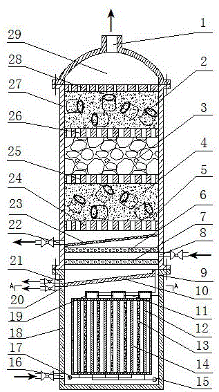
[0037] A proton membrane electrocatalytic flue gas desulfurization and denitrification device. Such as figure 1 As shown, the device is composed of a catalytic reaction absorption tower and an electrolytic reactor, and the lower end of the catalytic reaction absorption tower and the upper end of the electrolytic reactor are connected with the central line as a whole.

[0038] The structure of the catalytic reaction absorption tower is as follows: figure 1 As shown: the top cover 29 and the tower body 5 are fixedly connected to the center line through the flange, the longitudinal section of the top cover 29 is arc-shaped, and the center of the top cover 29 is provided with an exhaust port 1 .

[0039] The structure of tower body 5 is as figure 1 As shown: the tower body shell 27 is a hollow cylinder, and the height and outer diameter ratio of the tower body shell 27 is 3:1~4:1. Inside the tower shell 27, there are baffles 28, a first desulfurization and denitrification catal...

Embodiment 2

[0053] A proton membrane electrocatalytic flue gas desulfurization and denitrification device. Except following technical parameter, all the other are with embodiment 1:

[0054] The height and outer diameter ratio of the tower shell 27 is 4:1~5:1.

[0055] The ratio of the height to the outer diameter of the electrolytic reactor shell 18 is 1.2:1~1.3:1.

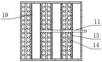
[0056] The electrolytic reaction chamber is in the shape of a box, and there are 15 slots uniformly opened on the inner wall of the top plate, bottom plate, front side plate and rear side plate of the box body, and each slot is in the shape of a “mouth”. The plane where the two slots are located is parallel to the left side panel of the cabinet. Proton membranes 13 are embedded in slots with even numbers, anode plates (14) are embedded in slots with sequence numbers 1, 5, 9 and 13, and cathode plates 12 are embedded in the remaining slots. A row of small holes is evenly opened between the slots on the bottom plate of the ...

Embodiment 3

[0058] A proton membrane electrocatalytic flue gas desulfurization and denitrification device. Except following technical parameter, all the other are with embodiment 2:

[0059] The electrolytic reaction chamber is in the shape of a box. There are 19 slots evenly opened on the inner wall of the box top, box bottom, box front side plate and box rear side plate. Each slot is in the shape of a "mouth". The plane where the two slots are located is parallel to the left side panel of the cabinet. Proton membranes 13 are embedded in slots with even numbers, anode plates 14 are embedded in slots with sequence numbers 1, 5, 9, 13 and 17, and cathode plates 12 are embedded in the remaining slots. The upper plane of the top plate of the box body is provided with 5 strip groove plates 19 .

[0060] This device can treat SO in the mixed flue gas 2 , NO X and CO 2 Purification can also recycle sulfur and methanol resources in the product. The specific steps are as follows:

[0061] ...


PUM

PropertyMeasurementUnit
thicknessaaaaaaaaaa
particle diameteraaaaaaaaaa
pore sizeaaaaaaaaaa

Abstract

The invention discloses a flue gas desulfurization and denitration device utilizing proton membrane electrocatalysis. The device is composed of a catalytic reaction absorption tower and an electrolytic reactor. The electrolytic reactor is communicated with the catalytic reaction absorption tower through a hydrogen gas opening (9) of a guide plate (10). A tower body shell (27) of the catalytic reaction absorption tower is internally provided with a baffle (28), a first desulfurization and denitration catalyst packing layer (2), an upper bearing plate (26), a carbon fixation catalyst packing layer (3), a middle bearing plate (25), a second desulfurization and denitration catalyst packing layer (4), a lower bearing plate (24), a solid-liquid separator (23), a flue gas distributor (6) and a hydrogen gas distributor (7) in sequence from the upper end to the position close to the lower end. The electrolytic reactor is internally provided with an electrolytic reaction chamber. The electrolytic reaction chamber is internally provided with anode plates (14) and cathode plates (12), and the anode plates (14) are separated from the cathode plates (12) through proton membranes (13). The flue gas desulfurization and denitration device has the advantages of being simple in structure, small in occupied area, low in investment and operation cost, high in flue gas purification efficiency and good in product recycling effect.

Description

technical field [0001] The invention belongs to the technical field of flue gas desulfurization and denitrification devices. Specifically relates to a proton membrane electrocatalytic flue gas desulfurization and denitrification device. Background technique [0002] With the continuous acceleration of industrialization and urbanization in our country, industry occupies an increasing proportion in the growth of the national economy, and human demand for energy is also increasing day by day. The consumption of natural resources such as coal, oil, and natural gas is increasing day by day, resulting in air pollution. A few days ago, the smog weather in many cities across the country has challenged the living environment of human beings. Harmful gases in the atmosphere have attracted much attention from all walks of life at home and abroad because of their characteristics of strong toxicity, wide spread and difficulty in control. SO 2 , NO X and CO 2 and other flue gas as th...

Claims


Application Information

Patent Timeline
Patent Type & Authority Patents(China)
IPC IPC(8): B01D53/86B01D53/60B01D53/62C25B1/04
CPCY02E60/36
Inventor 王黎张佳凤孙杨胡宁王捷雷蕾
Owner WUHAN UNIV OF SCI & TECH
Why Eureka
Try Eureka