
Mooring system based on multi-rotor flight platform

A multi-rotor aircraft and flight platform technology, applied in the system field of unmanned aerial vehicles, can solve problems such as uncontrollable systems, insufficient load capacity, and reduced system reliability, so as to improve system reliability, increase carrying capacity, and reduce line loads. The effect of cable weight

Active Publication Date: 2015-12-02
南京国业科技有限公司
View PDF6 Cites 27 Cited by
  • Summary
  • Abstract
  • Description
  • Claims
  • Application Information

AI Technical Summary

Problems solved by technology

[0005] There are six rotating parts of the platform (only referring to the rotor system). Among them, the central coaxial dual-rotor is the lift-providing part, and the peripheral quad-rotor system is the attitude control part. If there is a problem with the central multi-rotor system, not only will it lead to insufficient lift, It will also cause the imbalance of the central moment; if a rotor in the quadrotor fails, the system will enter an uncontrollable state
The failure of each rotating part is fatal to the system itself, and the system reliability is low
[0006] However, after combining the central coaxial dual-rotor and the multi-rotor system, the control system needs to consider the control of the central coaxial dual-rotor and the control of the multi-rotor at the same time. There are many control variables to be considered, and the control logic is more complicated. Too complex system control will also reduce the reliability of the system
[0007] In addition, the load capacity of the system is 6kg, which is insufficient for the special monitoring and communication equipment that the moored platform hopes to carry, and belongs to the small moored platform

Method used


Image

  • Mooring system based on multi-rotor flight platform
  • Mooring system based on multi-rotor flight platform
  • Mooring system based on multi-rotor flight platform

Examples


Embodiment Construction

[0060] The specific embodiments of the present invention will be further described in detail below in conjunction with the accompanying drawings.

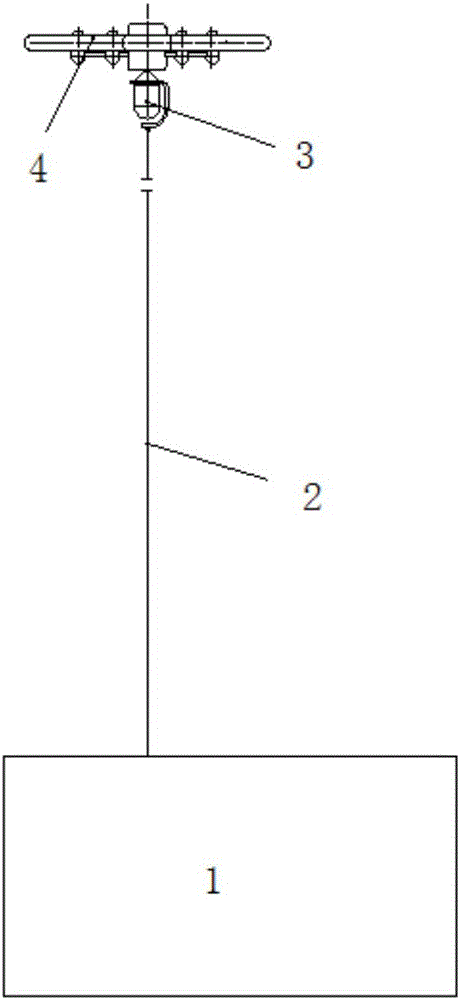
[0061] Such as figure 1 as shown, figure 1 Schematic diagram of the structure of the mooring system based on the multi-rotor flight platform provided by the present invention; the mooring system based on the rotor flight platform provided by the present invention includes the following subsystems: ground equipment, tethering cables, multi-rotor aircraft and mission equipment.

[0062] Wherein, the task equipment is installed on the equipment mounting rack of the multi-rotor aircraft, and the two ends of the mooring cable are respectively connected to the mounting rack and the ground equipment, thereby connecting the multi-rotor aircraft and the ground equipment.

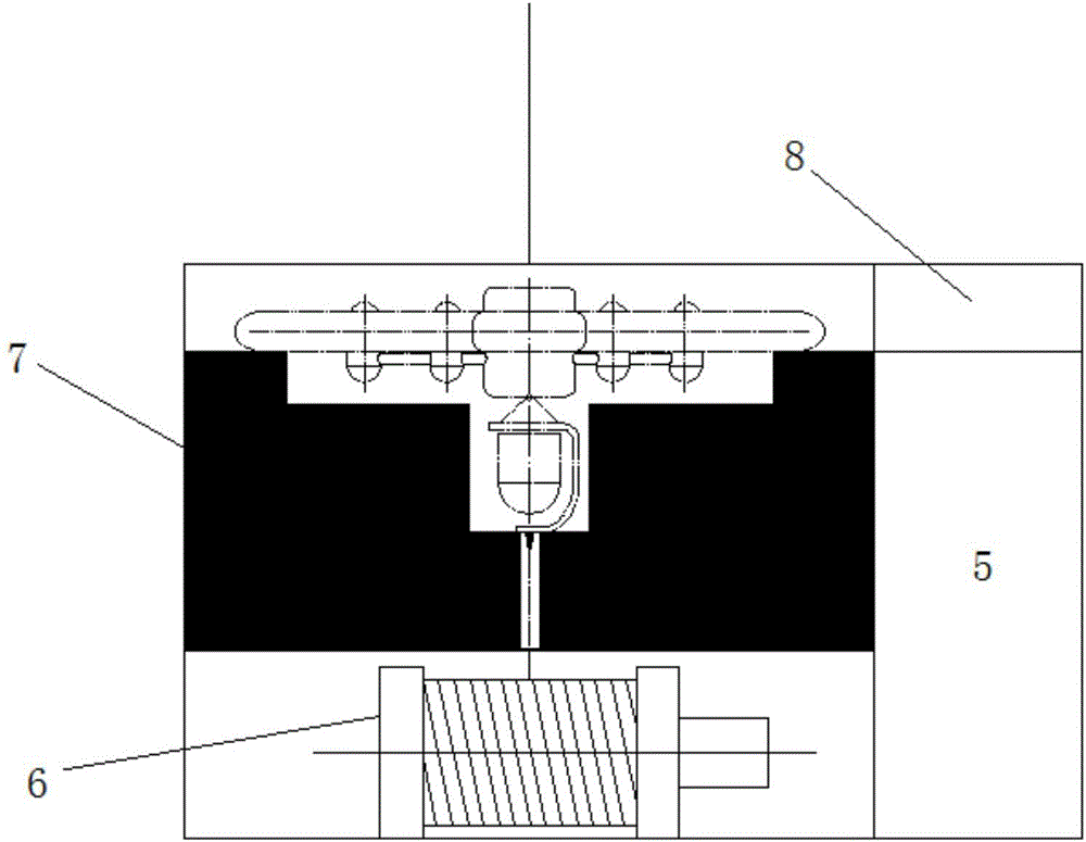
[0063] Such as figure 2 as shown, figure 2 It is a schematic structural diagram of the ground equipment of the mooring system based on the multi-rotor flying platfor...


PUM


Abstract

The invention provides a mooring system based on a multi-rotor flight platform. The mooring system comprises ground equipment, a mooring cable, a multi-rotor air vehicle and mission equipment, wherein the mission equipment is mounted on an equipment mounting frame of the multi-rotor air vehicle, and the two ends of the mooring cable are respectively connected with the equipment mounting frame and the ground equipment; and rotors of the multi-rotor aircraft are symmetrically distributed on the left and right two sides of the air vehicle. The multi-rotor system provided by the invention is a lift system as well as an attitude control system and can be backed up for each other. When single rotor fails, the lift of the system cannot suddenly vary, and control can also be converted to a low-order rotor mode. The reliability of the system is effectively improved.

Description

technical field [0001] The invention relates to a system in the field of unmanned aerial vehicles, in particular to a mooring system based on a multi-rotor flying platform. Background technique [0002] The tethering system is mainly to tie the flight platform equipped with special communication equipment and photoelectric equipment to the anchor point on the ground through cables, so as to realize the long-term communication network establishment and the monitoring of the established target. Unmanned aerial vehicles such as balloons, airships, and ducted aircraft have the characteristics of vertical take-off and landing and stable hovering, and are widely used as tethered platforms in the fields of reconnaissance, communication, and aerial photography. [0003] Although tethered balloons or tethered airships can stay in the air for a long time, they are very bulky, inconvenient to maneuver, have poor wind resistance, and the helium filled with them is expensive and the main...

Claims


Application Information

Patent Timeline
IPC IPC(8): B64F3/02
Inventor 姚霞林李余冬
Owner 南京国业科技有限公司
Learn More