Fluid artificial muscle driving and controlling system
A fluid artificial muscle and control system technology, which is applied in the application fields of robots and machinery, can solve the problems of inability to drive and control fluid artificial muscles well, difficulty in driving and controlling, and increased economic costs, and achieve easy installation and operation, The effect of low cost and increased smoothness of motion
- Summary
- Abstract
- Description
- Claims
- Application Information
AI Technical Summary
Problems solved by technology
Method used
Image

Examples
specific Embodiment approach 1
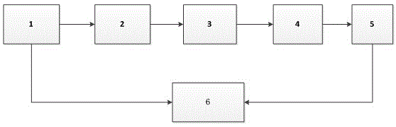
[0012] Specific implementation mode one: as figure 1 As shown, the fluid artificial muscle drive and control system provided by this embodiment mainly includes a pressure transmitter 1 , a fluid artificial muscle 2 , a hydraulic cylinder 3 , a ball screw 4 , a motor 5 , and a PC control terminal 6 . One end of the fluid artificial muscle 2 is connected to the pressure transmitter 1, and the other end is in airtight communication with the hydraulic cylinder 3; the two ends of the ball screw 4 are respectively connected to the end of the piston rod of the hydraulic cylinder 3 and the motor 5; the motor 5 and the pressure transmitter The device 1 is connected to the PC control terminal 6 respectively.
[0013] work process:
[0014] When the PC control terminal 6 sends a signal, the motor 5 will drive the ball screw 4 to rotate, and the ball screw 4 will drive the piston of the hydraulic cylinder 3 to advance along the axis of the hydraulic cylinder, and the internal pressure of...
specific Embodiment approach 2
[0015] Specific embodiment two: the difference between this embodiment and specific embodiment one is that the relationship between the number of revolutions of the motor 5 and the output pressure of the fluid artificial muscle 2 can be obtained through experiments, and then the pressure transmitter 1 is not used, but the pressure of the motor 5 is directly used. The number of revolutions is fed back to the PC control terminal 6 as a corresponding parameter, and then the drive and control of the fluid artificial muscle 2 are realized directly through the motor 5 .
specific Embodiment approach 3
[0016] Embodiment 3: The difference between this embodiment and Embodiment 1 or 2 is that the pressure transmitter 1, the motor 5 and the PC control terminal 6 can be connected by wires, and the wire connection length is determined according to actual application needs; In addition, a wireless signal sending and receiving device can also be installed on the motor 5 , the pressure transmitter 1 and the PC control terminal 6 to realize long-distance wireless remote control.
PUM
 Abstract
Description
Claims
Application Information
 - Generate Ideas
- Intellectual Property
- Life Sciences
- Materials
- Tech Scout
- Unparalleled Data Quality
- Higher Quality Content
- 60% Fewer Hallucinations
Browse by: Latest US Patents, China's latest patents, Technical Efficacy Thesaurus, Application Domain, Technology Topic, Popular Technical Reports.
© 2025 PatSnap. All rights reserved.Legal|Privacy policy|Modern Slavery Act Transparency Statement|Sitemap|About US| Contact US: help@patsnap.com