Sine wave generating circuit and method for measuring resistance and battery tester

A technology for measuring resistance and generating circuits, applied in the direction of measuring electricity, measuring electrical variables, components of electrical measuring instruments, etc., can solve the problems of frequency offset, shortened use time, large power consumption, etc., and achieves less CPU resource occupation. , the effect of increasing use time and reducing energy consumption

Active Publication Date: 2015-12-02
广州益业机电设备科技有限公司
View PDF7 Cites 4 Cited by
  • Summary
  • Abstract
  • Description
  • Claims
  • Application Information

AI Technical Summary

Problems solved by technology

The disadvantage of this circuit is: the amount of positive feedback is difficult to control. If the amount of feedback is less than 1 times, the circuit cannot overcome the internal loss and thus cannot generate self-excited oscillation. If the amount of feedback is too large, the circuit will output a square wave instead of a sine wave In addition, it is necessary to add a frequency selection network to achieve a single frequency output, otherwise the circuit will oscillate in a wide frequency range and generate many harmonics; at the same time, even if it can output a single frequency sine wave, the circuit itself is easily affected by the outside world. Environmental influences, such as temperature, humidity and other factors, cause frequency d

Method used


Image

  • Sine wave generating circuit and method for measuring resistance and battery tester
  • Sine wave generating circuit and method for measuring resistance and battery tester
  • Sine wave generating circuit and method for measuring resistance and battery tester

Examples


Embodiment Construction

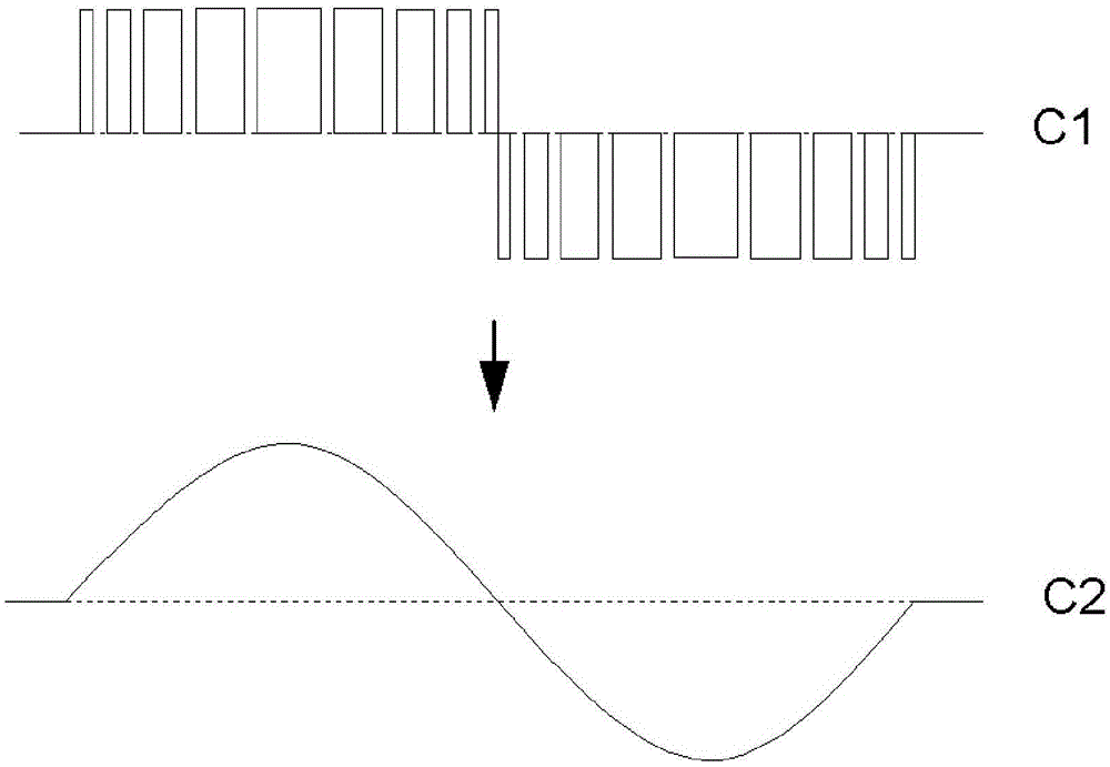
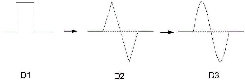
[0034] see Figure 4 , which is a sine wave generating circuit for measuring resistance of the present invention, including a CPU (central processing unit) 1, a gate shaping circuit 2, an operational amplification unit 3, a filtering unit 4 and a shaping amplification unit 5 connected in series. see Figure 5 , which is a schematic diagram of signal waveform conversion in the present invention. First, a square wave B1 is generated by the CPU1, and then converted into a ladder-shaped waveform B2 by a gate shaping circuit 2. After the waveform passes through an operational amplification unit 3, a filter unit 4 and a shaping amplification unit 5, Finally converted to sine wave B3. The sine wave B3 is used as a reference signal when the battery tester measures resistance.

[0035] Wherein, the CPU1 uses a program to generate a square wave pulse B1 with a fixed duty cycle, the duty cycle of which can be set according to needs, and outputs to the gate shaping circuit 2 in two ways...


PUM


Abstract

The invention provides a sine wave generating circuit for measuring resistance. The circuit comprises a CPU, a gate shaping circuit and a shaping and amplifying unit. The CPU generates two paths of square wave signals with a fixed duty cycle and transmits the signals to the gate shaping circuit. The gate shaping circuit converts the square wave signals into stepped waveform signals with alternating peaks and troughs. The shaping and amplifying unit converts the stepped waveform signals into sine wave signals. The sine wave generating circuit and the method for measuring resistance provided by the invention have the advantages of stable effect, low power consumption, high precision and are especially suitable for an occasion with large environment change and limited power supply such as wild, and the invention also provides a batter tester.

Description

technical field [0001] The invention relates to a sine wave generating circuit and method, in particular to a sine wave generating circuit and method for measuring resistance, and a storage battery tester. Background technique [0002] The battery tester, also known as the battery measuring instrument, is an analysis and testing equipment mainly used to measure the battery, which includes measuring the voltage, current, resistance, temperature, etc. of the battery, and then judging the working ability and health status of the battery. In the process of measuring resistance, the battery tester needs to use the sine wave as the reference signal for feedback and comparison. The advantage is that the sine wave is an alternating signal, which can avoid the DC interference of the battery and improve the detection accuracy. [0003] In the prior art, there are several methods for generating sine waves for measuring the resistance of the storage battery as follows: [0004] One is ...

Claims


Application Information

Patent Timeline
IPC IPC(8): G01R1/28G01R31/36
Inventor 陈国宏梁登黄业开何善灿
Owner 广州益业机电设备科技有限公司
Why Eureka
Try Eureka