A Fault Diagnosis Method for Commutation Failure of UHVDC Transmission System

A technology for UHV DC and power transmission systems, applied in the direction of measuring electricity, measuring electrical variables, measuring current/voltage, etc., and can solve problems such as commutation failure

Active Publication Date: 2018-03-06
KUNMING UNIV OF SCI & TECH
View PDF9 Cites 0 Cited by
  • Summary
  • Abstract
  • Description
  • Claims
  • Application Information

AI Technical Summary

Problems solved by technology

[0003] The invention provides a commutation failure fault diagnosis method for UHV DC transmission system, which is used to distinguish line short circuit fault and commutation failure in UHV DC transmission system, and solves the transition of the current minimum turn-off angle discrimination method at a certain value The problem of judging commutation failure when a short circuit occurs in the resistance

Method used


Image

  • A Fault Diagnosis Method for Commutation Failure of UHVDC Transmission System
  • A Fault Diagnosis Method for Commutation Failure of UHVDC Transmission System
  • A Fault Diagnosis Method for Commutation Failure of UHVDC Transmission System

Examples


Embodiment 1

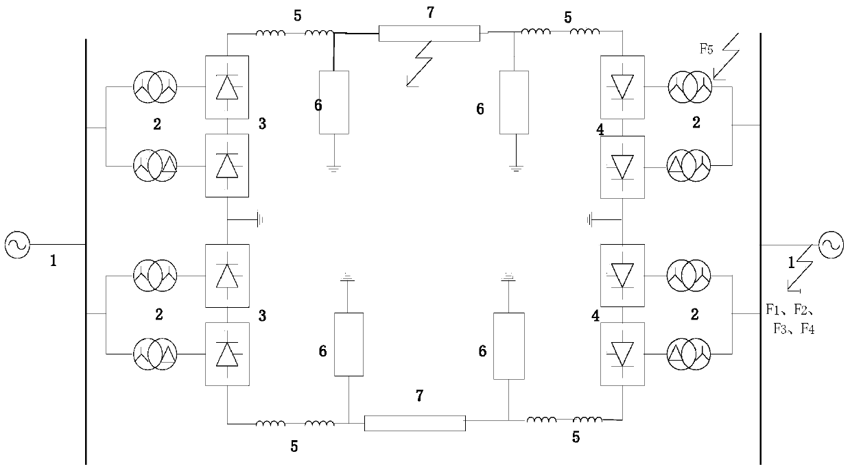
[0038] Embodiment 1: as Figure 1-9 As shown, a commutation failure fault diagnosis method for UHVDC transmission system, the specific steps of the UHVDC transmission system commutation failure fault diagnosis method are as follows:

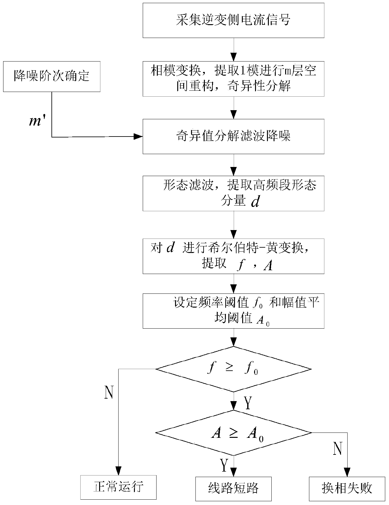
[0039] Step1. After the UHV DC transmission system fails, the data acquisition device on the inverter side collects the fault current data within the time window 5ms after the arrival of the first wave of the fault current traveling wave;

[0040] Step2. Perform phase-to-mode transformation on the collected current signal, extract its 1 modulus, and perform m-layer phase space reconstruction to obtain the reconstructed matrix;

[0041] Step3. Singular value decomposition is performed on the reconstructed matrix, and an appropriate noise reduction order m' is selected according to the distribution trend of the singular value, and then the DC current signal is denoised;

[0042] Step4. Send the noise-reduced signal to the morphological filter to e...

Embodiment 2

[0047] Embodiment 2: as Figure 1-9 As shown, a commutation failure fault diagnosis method for UHVDC transmission system, the specific steps of the UHVDC transmission system commutation failure fault diagnosis method are as follows:

[0048] Step1. After the UHV DC transmission system fails, the data acquisition device on the inverter side collects the fault current data within the time window 5ms after the arrival of the first wave of the fault current traveling wave;

[0049] Step2. Perform phase-to-mode transformation on the collected current signal, extract its 1 modulus, and perform m-layer phase space reconstruction to obtain the reconstructed matrix;

[0050] Step3. Singular value decomposition is performed on the reconstructed matrix, and an appropriate noise reduction order m' is selected according to the distribution trend of the singular value, and then the DC current signal is denoised;

[0051] Step4. Send the noise-reduced signal to the morphological filter to e...


PUM


Abstract

The invention relates to a commutation failure fault diagnosis method of an ultra-high voltage direct current transmission system, and belongs to the technical field of fault diagnosis of a high voltage direct current transmission system. The present invention first performs layered reconstruction on the extracted DC current signal sequence; then performs noise reduction processing on the signal, filters it with a morphological filter after processing, and extracts its high-frequency component; performs Hilbert processing on the high-frequency component ‑Huang transform, find the maximum instantaneous frequency f and the average value A of the intrinsic mode function components, set the frequency threshold f0 and the average value threshold A0 of the amplitude, if f≥f0, the system breaks down, if not established, the system Normal operation; if the system fails, it is judged whether A≥A0 is established, and if it is established, it is a line short circuit fault, otherwise it is a commutation failure fault. Therefore, the present invention can accurately distinguish the operating state of the system, commutation failure faults, and line short circuit faults.

Description

technical field [0001] The present invention relates to a commutation failure fault diagnosis method for UHVDC transmission system, in particular to a UHVDC transmission system commutation method using singular value decomposition (SVD)-morphological filter and Hilbert-Huang (HHT) transformation A phase failure fault diagnosis method belongs to the technical field of fault diagnosis of high-voltage direct current transmission systems. Background technique [0002] At present, the techniques for judging commutation failures in DC transmission systems are mainly the minimum turn-off angle discrimination method and the minimum voltage drop method. However, these methods have certain limitations. When the line passes through a certain value of transition resistance and a short circuit occurs, the minimum turn-off angle will also be lower than the limited minimum value. In this case, the commutation failure detection device will The short-circuit fault is judged as commutation f...

Claims


Application Information

Patent Timeline
Patent Type & Authority Patents(China)
IPC IPC(8): G01R19/165G01R23/02G01R31/02
Inventor 陈仕龙王燕武毕贵红杨具瑞荣俊香罗璐李建平黄钰淇
Owner KUNMING UNIV OF SCI & TECH
Why Eureka
Try Eureka