Light guide, laser light source and laser display system

A technology of light guides and light guide rods, applied in light guides, optical fiber light guides, light guides of lighting systems, etc., can solve the problems that the device is not suitable for mass production, the manufacturing process of the light guide plate module is complicated, and the acrylic plate is not resistant to high temperature, etc., to improve the picture High quality, improved viewing comfort, and low cost effects

Active Publication Date: 2019-06-14
HANGZHOU HONGSHI TECH
View PDF7 Cites 0 Cited by
  • Summary
  • Abstract
  • Description
  • Claims
  • Application Information

AI Technical Summary

Problems solved by technology

Although these methods weaken the influence of speckle, the system is more complex
[0003] Invention name: Laser display system for dissipating speckle, publication number: CN 104345470A The invention patent application discloses a device for eliminating speckle by adding a light guide plate module to the laser light source module and the display panel module to destroy the coherence of laser light , but the light guide plate module it uses is made by adding light-scattering material particles during the casting process of the acrylic plate. There are several problems with this light guide plate module. A lot of reflections, thereby reducing the output optical power, the second is that the acrylic plate is not resistant to high temperature, and the third is that the manufacturing process of the light guide plate module is complicated, so this device is not suitable for mass production

Method used


Image

  • Light guide, laser light source and laser display system
  • Light guide, laser light source and laser display system
  • Light guide, laser light source and laser display system

Examples


Embodiment 1

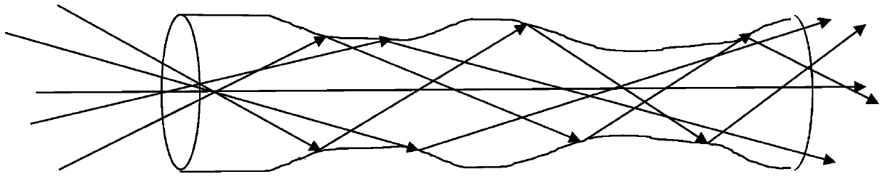
[0033] Such as figure 1 As shown, the light guide provided in this embodiment is a light guide rod with variable diameter. The radial size of the light guide rod changes gradually along the propagation direction of the optical path for multiple times, and the multiple changes are: from large to small and from small to large multiple times or From small to large and multiple times from large to small, the radial size of the light guiding rod can change from 0.1mm to 10cm. Before the light guiding rod is set in the laser source or the laser display system, the shape of its variable diameter has been made.

Embodiment 2

[0035] The light guide provided in this embodiment is a variable-diameter optical fiber. The radial size of the optical fiber changes gradually along the propagation direction of the optical path for multiple times, and the multiple changes are: from large to small and from small to large multiple times or from small to large Large and changed multiple times from large to small, the range of the radial size of the optical fiber is: 0.01 μm to 10 μm. Before the optical fiber is arranged in the laser source or the laser display system, the shape of the variable diameter has been made.

Embodiment 3

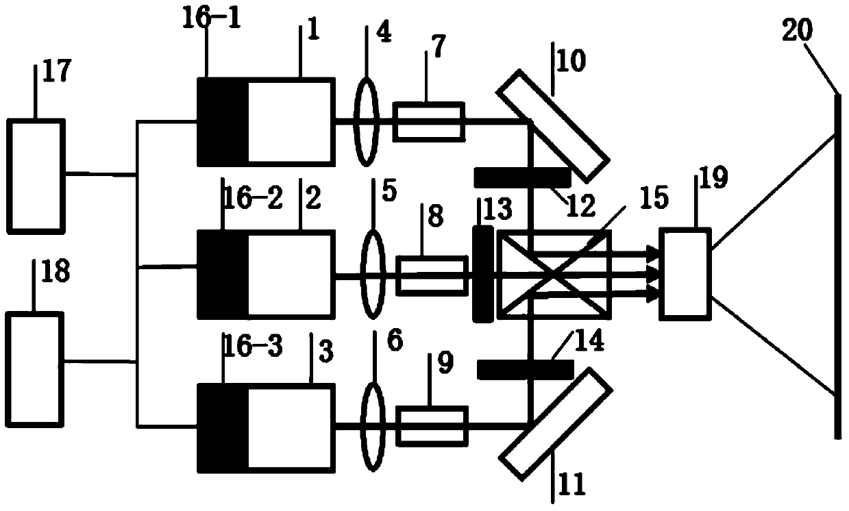
[0037] Such as figure 2 As shown, the laser light source provided in this embodiment includes a laser module and a light guide whose radial size gradually changes multiple times along the propagation direction of the light path, and the light guide is arranged on the output light path of the laser module. Atoms are stimulated to emit photons, and the laser is a photon queue composed of these photons. The photons in the laser have the same frequency, phase and polarization state, so the laser has the characteristics of good monochromaticity, good directionality, and good coherence. After the laser light emitted by the laser unit in the laser module enters the light guide, because the radial size of the light guide changes gradually along the propagation direction of the optical path for many times, the laser light will randomly refract and scatter when propagating in the light guide, and the optical path of the laser light will change. Change, thereby changing the phase of the...


PUM


Abstract

The invention discloses a light guide, a laser source and a laser display system. The laser source comprises at least one laser module and at least one light guide positioned at an output light path of the corresponding laser module, the radial size of the light guide is gradually changed by multiple times along a light path, the light path of laser emitted from the laser module is changed after the laser enters the light guide, thus eliminating coherence of the laser. The technical solution in the invention can be widely applied to various laser display systems, and has effects of inhibiting a speckle spot phenomenon in the laser display system, improving picture quality, improving brightness, uniformity and color saturation of a picture, and enhancing viewing comfort of the picture.

Description

technical field [0001] The invention relates to the field of laser display. More particularly, it relates to light guides, laser light sources and laser display systems. Background technique [0002] Laser has high brightness, so laser display is easier to reach the large-screen display of the geometric resolution limit of human eyes; laser is a line spectrum, such as the spectral width of laser is 5nm, and the spectral width of existing display is 40nm, then the color that laser display can present The number is about 500 times higher than that of the existing display, so the laser display can achieve double high-definition; at the same time, the laser has a higher color saturation, and the area of ​​the formed chromaticity triangle can be made as large as possible by selecting the three primary color wavelengths close to the vertex angle of the chromaticity triangle Larger, displaying more real and richer colors in nature, and true three-dimensional display can be realize...

Claims


Application Information

Patent Timeline
Patent Type & Authority Patents(China)
IPC IPC(8): G02B6/00G02B27/48
CPCG02B6/0006G02B27/48
Inventor 刘新厚许祖彦毕勇刘新建李世元
Owner HANGZHOU HONGSHI TECH
Why Eureka
Try Eureka