
DLP projection system with high contrast and high light energy utilization rate

A projection system and high-contrast technology, applied in the field of laser projection, can solve the problems of affecting the display effect, difficult installation, difficult heat dissipation, etc., and achieve the effects of suppressing speckle, improving light utilization, and reducing stray light.

Pending Publication Date: 2022-05-31
CHINA JILIANG UNIV
View PDF8 Cites 0 Cited by
  • Summary
  • Abstract
  • Description
  • Claims
  • Application Information

AI Technical Summary

Problems solved by technology

But there is a flaw in this solution: more light entering the image system also means more uncontrolled light entering the image system
But there are following defects in this scheme: (1) it is difficult to align the lens with the asymmetric aperture, which will increase the manufacturing cost
(2) The asymmetric aperture cuts off the uncontrolled aperture, and the contrast of the DLP projection system is reduced, because the excess scattered light may hit the screen through multiple reflections in the imaging system
However, this solution has the following defects: (1) Due to the coherence of the laser, speckle will appear in the displayed image, which affects the display effect; (2) The laser must pass through three sets of dichroic mirrors, and each dichroic mirror In general, light energy will be lost, the cost of the dichroic mirror is high, and the incident angle of the incident light is strictly required. During the production or transportation process, the incident light cannot be incident on the dichroic mirror due to the change of the position of the component. (3) When the DMD is working, the light in the steady state and the off state still enters the image system in the form of stray light, resulting in a decrease in contrast, and the light energy utilization rate of the entire system is low ,complex structure
[0006] It can be seen that the existing laser projection system scheme cannot keep the stray light in the steady state and Off state away from the image system when the DMD is working, the laser speckle cannot be effectively suppressed, and there are low utilization of light energy, complex structure, and components. More, larger volume, higher cost, difficulty in heat dissipation, etc.

Method used


Image

  • DLP projection system with high contrast and high light energy utilization rate
  • DLP projection system with high contrast and high light energy utilization rate
  • DLP projection system with high contrast and high light energy utilization rate

Examples


Embodiment

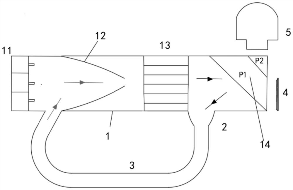
[0069] The structure and working process of a DLP projection system with high contrast ratio and high light energy utilization rate disclosed by the present invention will be described in detail below with reference to the accompanying drawings.

[0070] The DLP projection system disclosed in this embodiment includes: a light guide rod 1, a DMD 4, a projection lens 5 and a light source repeated collection device;

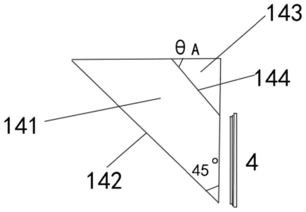
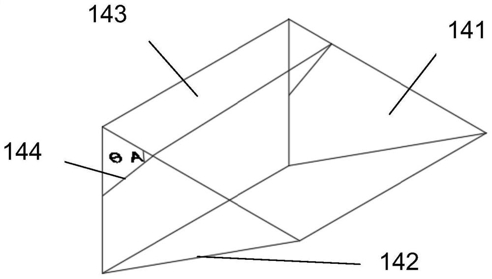
[0071] The light guide rod 1 is in the shape of a rectangular parallelepiped, and an LD surface light source 11, a compound parabolic concentrator 12, a GIRN lens 13 and an optical separator 14 are integrated in it in sequence;

[0072] LD surface light source 11 selects OSRAM company's professional laser light source for projector lighting, which is selected from red, green and blue light sources; the wavelength of the red LD surface light source is 650nm, the power is 0.5w, and the model is SPL CG65; the green LD surface light source is SPL CG65 The wavelength of ...


PUM


Abstract

The invention discloses a DLP projection system with high contrast and high light energy utilization rate. The DLP projection system comprises a light guide rod, a DMD and a projection lens, an LD area light source, a compound paraboloid condenser, a GIRN lens and a light separator are sequentially integrated in the light guide rod. The DLP projection system further comprises a light source repeated collection device communicated with the light guide rod. The DLP projection system disclosed by the invention can effectively reduce stray light in a stable state and an Off state when the DMD works, so that the contrast ratio and the light energy utilization rate are effectively improved, laser speckles are effectively controlled, and the DLP projection system is simple in light path, few in used components, small in size and low in cost.

Description

technical field [0001] The invention relates to the technical field of laser projection, in particular to a DLP projection system with high contrast ratio and high light energy utilization rate. Background technique [0002] In recent years, as people have higher and higher requirements for the quality of images projected by projectors, traditional light sources can no longer meet people's needs. In the selection of projector light sources, people have turned their attention to the field of laser lighting. Compared with traditional light sources, laser projectors have the advantages of wide color gamut, high contrast ratio, and high brightness. [0003] DLP is a technology used in all-digital projection display systems, which is based on the digital micromirror device (DMD) developed by Texas Instruments (TI), which is a fast reflective digital optical switch based on a semiconductor substrate. It is both a micro-electromechanical system (MEMS) and a spatial light modulator...

Claims


Application Information

Patent Timeline
Patent Type & Authority Applications(China)
IPC IPC(8): G03B21/00G03B21/14G03B21/20
CPCG03B21/008G03B21/142G03B21/206G03B21/208G03B21/2066
Inventor 王乐崔涛钱立勇沈泽涛张宏邾强强翟玥
Owner CHINA JILIANG UNIV
Learn More