Laser lighting device, laser projection system and laser display system

A laser lighting and laser light source technology, applied in the field of laser lighting, can solve the problems of insignificant speckle effect, limited scope of application, and difficulty in practical application, and achieve the effects of improving viewing comfort, simple manufacturing process, and reducing speckle contrast

Active Publication Date: 2017-08-25
HANGZHOU HONGSHI TECH
View PDF5 Cites 0 Cited by
  • Summary
  • Abstract
  • Description
  • Claims
  • Application Information

AI Technical Summary

Problems solved by technology

[0005] Among the above four methods, the first and second methods are simple and cheap, but due to limited statistical independence, the effect of reducing speckle is not significant and cannot meet the needs of practical applications; the third method can effectively eliminate Laser coherent speckle, but due to the mechanical vibration of the screen, the scope of application is greatly limited; the fourth method is the most reasonable and effective method to solve the speckle from the physical mechanism of speckle formation
However, the existing broadband red, green, and blue primary color lasers are technically difficult to obtain. Even if the broadband three primary color lasers can be produced, there are problems of low efficiency, high cost, and difficulty in practical application.

Method used


Image

  • Laser lighting device, laser projection system and laser display system
  • Laser lighting device, laser projection system and laser display system
  • Laser lighting device, laser projection system and laser display system

Examples


Embodiment 1

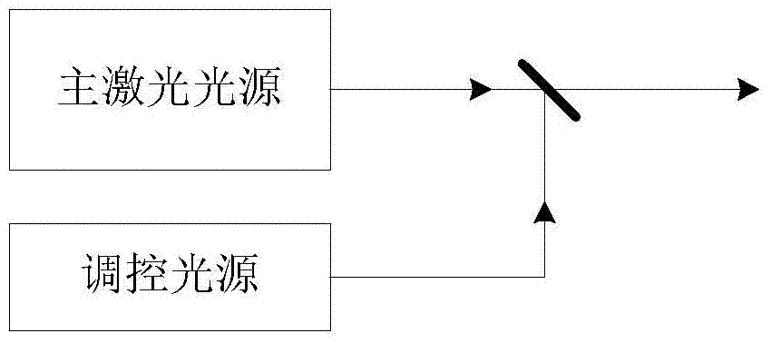
[0047] Such as figure 2 As shown, the laser lighting device provided by this embodiment includes a monochromatic laser light source and a monochromatic control light source, and the wavelength difference between the control light source and the laser light source is greater than or equal to 5 nm and less than or equal to 30 nm. The output beams of the control light source and the laser light source pass through the optical system and exit through a common optical path. In this embodiment, the laser light source may be a red light source, a blue light source or a green light source. For example, the red light source may be a 635nm semiconductor laser, for example, the blue light source may be a 445nm semiconductor laser, for example, the green light source may be a 532nm all-solid-state laser. The red light source, blue light source, or green light source may use corresponding control light sources such as 650nm, 515nm, 460-470nm semiconductor lasers or LEDs with a wavelength d...

Embodiment 2

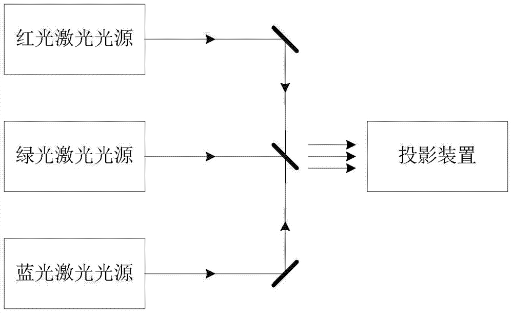
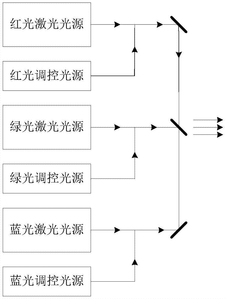
[0049] Such as image 3 As shown, the laser lighting device provided by this embodiment includes a set of three primary color laser light sources and a control light source corresponding to the three primary color laser light sources. The three primary color laser light sources are red, green, and blue three primary color laser light sources, and the corresponding three colors The regulated light sources are red, green, and blue regulated light sources. The output beam of the control light source and the laser beam of the laser light source pass through the optical system and exit through a common optical path. In this embodiment, the red and blue laser light sources in the three primary color light sources are semiconductor lasers with wavelengths of 635 nm and 445 nm, respectively, and the green light source is an all-solid-state laser with 532 nm. The red, green, and blue control light sources are 650nm, 515nm, 460~470nm semiconductor lasers or LEDs with a wavelength differe...

Embodiment 3

[0051] Such as Figure 4 As shown, the laser illumination device provided in this embodiment includes a set of three primary color laser light sources and a control light source, the three primary color laser light sources are red, green, and blue laser light sources, and one control light source is a green light control light source. The green light control light source and the three-primary color laser light source are combined to emit a common light path. In this embodiment, the red, green, and blue laser sources of the three primary color laser sources are semiconductor lasers with wavelengths of 635 nm and 445 nm, respectively, and the green light source is an all-solid-state laser with 532 nm. The green light source is a semiconductor laser with a wavelength of 515 nm or an LED with a wavelength difference of 5-30 nm from the green laser in the tri-primary laser light source. The power ratio of the laser light source and the light source is 3:1.


PUM


Abstract

The invention discloses a laser lighting device, a laser projection system and a laser display system. The laser lighting device includes a main laser light source; at least one control light source, and the wavelength difference between the output beam of each control light source and the output laser beam of the main laser light source is greater than or equal to 5nm and less than It is equal to 30nm; the beam combining device is used to output the light beam of the control light source and the laser beam of the main laser light source in the same optical path. The technical solution of the present invention greatly reduces the speckle contrast by adding a control light source to the laser lighting device, thereby effectively suppressing the speckle phenomenon in the laser display screen.

Description

Technical field [0001] The invention relates to the technical field of laser illumination. More specifically, it relates to a laser illumination device, a laser projection system and a laser display system. Background technique [0002] Using laser as a light source, it can be applied to fields including laser projection display and liquid crystal laser backlight display, and has the advantages of wide color gamut, long life and high brightness. However, due to the high coherence of laser, the display picture has the disadvantage of laser coherent speckle. Laser coherent speckle is a kind of interference noise that appears on the retina due to the interaction of coherent wavelets scattered or reflected by laser light on a rough surface. Speckle appears as speckle noise on the screen, which will reduce the image quality and easily cause vertigo and eyestrain. It is one of the technical problems that need to be solved in the field of laser lighting (especially display technology)...

Claims


Application Information

Patent Timeline
Patent Type & Authority Patents(China)
IPC IPC(8): G03B21/20G02B27/48
Inventor 毕勇王东周孙敏远刘新厚王栋栋张文平高伟男
Owner HANGZHOU HONGSHI TECH
Why Eureka
Try Eureka