Quasi Z-source inverter with high boost gain

A source inverter, high boost technology, applied in the field of quasi-Z source inverter with high boost gain, can solve the problems of device voltage stress reduction, limited boost capability, insufficient boost capability, etc., to reduce device voltage Stress, improve the boosting ability, improve the effect of circuit safety

Inactive Publication Date: 2015-12-02
SHANGHAI UNIVERSITY OF ELECTRIC POWER
View PDF3 Cites 11 Cited by
  • Summary
  • Abstract
  • Description
  • Claims
  • Application Information

AI Technical Summary

Problems solved by technology

[0004] However, the Z-source inverter also has deficiencies, such as the high voltage stress of the Z-source inverter device, insufficient boosting capacity, etc.
The quasi-Z source inverter overcomes the shortcomings of the latter by making minor changes to the topology of the Z-source inverter, while retaining all the advantages of the Z-source inverter, and ca

Method used


Image

  • Quasi Z-source inverter with high boost gain
  • Quasi Z-source inverter with high boost gain
  • Quasi Z-source inverter with high boost gain

Examples


Embodiment

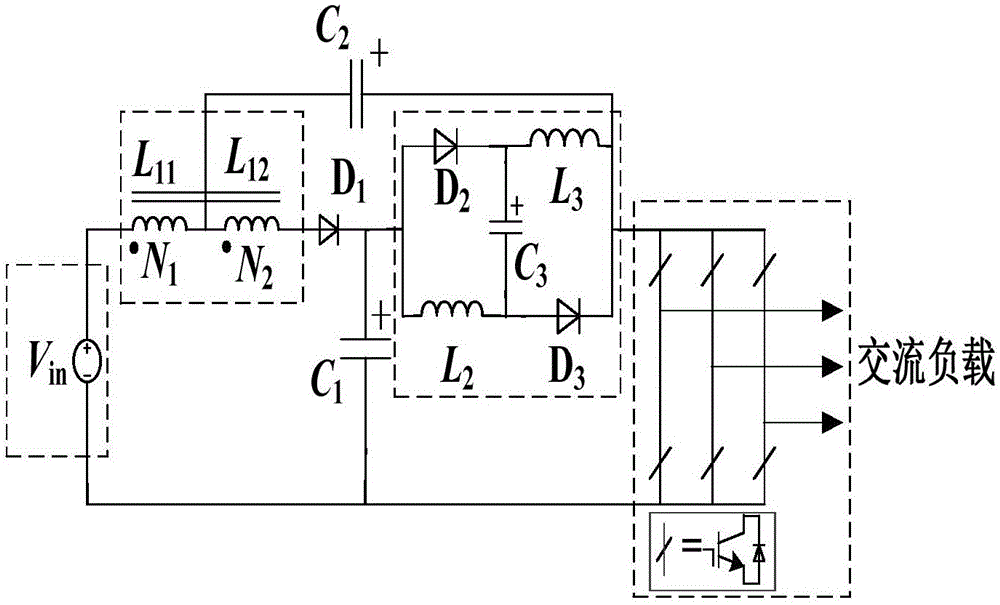
[0027] Such as figure 1 As shown, the high boost gain quasi-Z source inverter of the present invention includes a DC power supply V in A three-phase inverter composed of a high boost gain quasi-Z source boost network and a three-phase inverter bridge. The high boost gain quasi-Z source boost network is composed of a tap inductor, a switch inductor group, a first capacitor C 1 , the second capacitance C 2 and the first diode D 1 composition. The tapped inductance consists of N 1 Winding L 11 and N 2 Winding L 12 connected, the switched inductor group is formed by the second switched inductor L 2 , the third inductance L 3 , the third capacitor C 3 , the second diode D 2 and the third diode D 3 composition. The first capacitance C 1 , the second capacitance C 2 and the third capacitor C 3 It is a polar capacitor, and the capacitance value is equal, which is convenient for theoretical analysis, and at the same time, it can make the first capacitor C 1 and the thi...


PUM


Abstract

The invention relates to a quasi Z-source inverter with high boost gain. The quasi Z-source inverter comprises a DC power supply Vin, a quasi Z-source boost network, and a three-phase inverter. The quasi Z-source boost network comprises a tap inductor, a first diode D1, a first capacitor C1, a second capacitor C2, and a switched inductor group. When the three-phase inverter is in a non shoot-through state, the tap inductor charges the first capacitor C1 and the switched inductor group charges the second capacitor C2 in order to improve the boost capability of the Z-source inverter and reduce the voltage stress of the first capacitor C1, the second capacitor C2, and the switched inductor group. Compared with a product in the prior art, the quasi Z-source inverter uses single-stage structure and reduces circuit size and cost. A shoot-through zero vector enables the top bridge arm and the bottom bridge arm of an inverter bridge to be simultaneously switched on, thereby improving circuit security. The quasi Z-source inverter reduces voltage stress of devices while achieving high boost gain.

Description

technical field [0001] The invention relates to a power electronic converter, in particular to a quasi-Z source inverter with high boosting gain. Background technique [0002] With the increasing shortage of energy and serious environmental pollution, people pay more and more attention to clean energy, such as wind power generation, photovoltaic power generation, etc., which have developed rapidly in the industry. However, since the output voltage of some clean energy sources such as wind power and photovoltaic power generation will be affected by changes in natural environmental conditions, to solve the above problems, a DC-DC conversion circuit needs to be added before the inverter circuit. Such a structure will cause problems such as increased circuit cost and decreased conversion efficiency. In order to solve this problem, Professor Peng Fangzheng proposed a Z-source inverter. [0003] The Z source inverter couples the DC-DC conversion circuit with the DC-AC conversion...

Claims


Application Information

Patent Timeline
IPC IPC(8): H02M7/5387
Inventor 薛阳李华郁阚东跃江天博
Owner SHANGHAI UNIVERSITY OF ELECTRIC POWER
Why Eureka
Try Eureka