Eureka AIR delivers breakthrough ideas for toughest innovation challenges, trusted by R&D personnel around the world.

S-band continuous-wave solid-state high power amplification device

A solid-state power and amplifying device technology, applied in power amplifiers, amplifier protection circuit layout, improving amplifiers to reduce temperature/power supply voltage changes, etc. Narrow bandwidth and other problems, to achieve the effect of excellent amplitude and phase consistency, high power capacity and low insertion loss

Active Publication Date: 2015-12-02
河南方达空间信息技术有限公司
View PDF7 Cites 11 Cited by
  • Summary
  • Abstract
  • Description
  • Claims
  • Application Information

AI Technical Summary

Problems solved by technology

[0002] At present, the demand for S-band high-power amplifiers in communication systems is increasing rapidly. The existing S-band high-power amplifiers mostly use klystron power amplifiers developed by imported CPI companies. output powerP -1 All ≤1kW, which cannot meet the user's high-power, wide-band communication requirements
In addition, most of the existing S-band high-power amplifier power combiners use multi-level coaxial (microstrip line) synthesis, which is large in size, low in power, high in loss, and low in efficiency. The harmonic filter uses 1 / 4, 1 / 2 waveguide wavelength membrane chip filter, its structure size is large, loss is large, and debugging is complicated

Method used


Image

  • S-band continuous-wave solid-state high power amplification device
  • S-band continuous-wave solid-state high power amplification device
  • S-band continuous-wave solid-state high power amplification device

Examples


Embodiment Construction

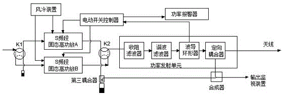
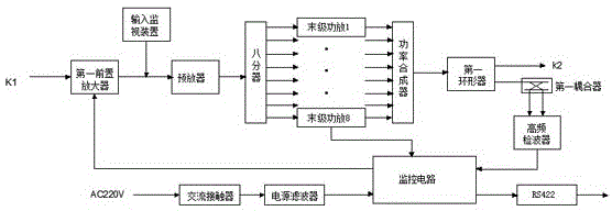
[0021] Such as figure 1 , figure 2 and image 3 As shown, the present invention is composed of S-band solid-state high-power amplifier A, S-band solid-state high-power amplifier B, a switch switching unit and a power transmitting unit. The switch switching unit includes a coaxial electric switch K1, a waveguide electric switch K2 and an electric switch controller. The shaft electric switch K1 is respectively connected to the input terminals of the S-band solid-state high-power amplifier A and the S-band solid-state high-power amplifier B, and the output terminals of the S-band solid-state high-power amplifier A and the S-band solid-state high-power amplifier B are respectively connected to one end of the waveguide electric switch K2. The other end of the switch K2 is connected to the input terminal of the power transmitting unit, the input terminal of the electric switch controller is connected to the power transmitting unit, and the output terminal of the electric switch co...


PUM


Abstract

The invention provides an S-band continuous-wave solid-state high power amplification device. The S-band continuous-wave solid-state high power amplification device consists of an S-band solid-state high power amplifier A, an S-band solid-state high power amplifier B, a switching unit and a power transmitting unit, wherein the switching unit comprises a coaxial electric switch, a waveguide electric switch and an electric switch controller; the input ends of the S-band solid-state high power amplifier A and the S-band solid-state high power amplifier B are connected with the coaxial electric switch respectively; the output ends of the S-band solid-state high power amplifier A and the S-band solid-state high power amplifier B are connected with one end of the waveguide electric switch respectively; the other end of the waveguide electric switch is connected with the power transmitting unit; the input end of the electric switch controller is connected with the output end of the power transmitting unit; and the output end of the electric switch controller is connected with the S-band solid-state high power amplifier A and the S-band solid-state high power amplifier B respectively. The S-band continuous-wave solid-state high power amplification device has the advantages of large instantaneous bandwidth, no tuning requirements, high efficiency, high reliability, easiness in operation, long service lifetime, low failure rate and the like.

Description

technical field [0001] The invention relates to a solid-state power amplifier in the communication field, in particular to an S-band continuous wave solid-state high-power amplifier device. Background technique [0002] At present, the demand for S-band high power amplifiers in communication systems is increasing rapidly. The existing S-band high power amplifiers mostly use klystron power amplifiers developed by imported CPI companies. output powerP -1 All ≤1kW, which cannot meet the user's high-power, wide-band communication requirements. In addition, most of the existing S-band high-power amplifier power combiners use multi-level coaxial (microstrip line) synthesis, which is large in size, low in power, high in loss, and low in efficiency. The harmonic filter uses 1 / 4, 1 / 2 waveguide wavelength membrane chip filter has large structure size, large loss and complicated debugging. Contents of the invention [0003] The purpose of the present invention is to provide an S-...

Claims


Application Information

Patent Timeline
Patent Type & Authority Applications(China)
IPC IPC(8): H03F1/30H03F1/52H03F3/20
Inventor 韩来辉严俊赵双领张宏伟
Owner 河南方达空间信息技术有限公司
Why Eureka
Eureka Blog
Learn More