Carbon dioxide capture system

A carbon dioxide and heat pump system technology, applied in chemical instruments and methods, separation of dispersed particles, air quality improvement, etc., can solve the problems of failure to use and transfer energy in time, low energy utilization rate of the system, low utilization rate of steam heat energy, etc.

Active Publication Date: 2015-12-09
CHINA PETROCHEMICAL CORP +3
View PDF5 Cites 7 Cited by
  • Summary
  • Abstract
  • Description
  • Claims
  • Application Information

AI Technical Summary

Problems solved by technology

The utilization rate of steam heat energy is very low, which leads to the low energy utilization rate of

Method used


Image

  • Carbon dioxide capture system

Examples


Embodiment Construction

[0147] The carbon dioxide capture system according to the present invention will be described in detail below with reference to the accompanying drawings.

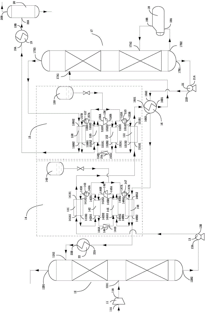
[0148] refer to figure 1 , The carbon dioxide capture system according to the present invention includes a fan 11, an absorption tower 12, a rich liquid pump 13, a first heat pump system 14, a second heat pump system 15, a lean-rich liquid heat exchanger 16, a desorption tower 17, and a reboiler 18 , a carbon dioxide cooler 19, a gas-liquid separator 20, a lean liquid pump 21 and a lean liquid cooler 22.

[0149] The blower 11 has: a blower inlet 11A for sucking in external carbon dioxide raw material gas; and a blower outlet 11B.

[0150] The absorption tower 12 has: the first inlet 12A1 of the absorption tower is communicated with the fan outlet 11B; the first outlet 12B1 of the absorption tower is arranged on the top of the absorption tower 12; the second inlet 12A2 of the absorption tower is arranged on the top of the...


PUM


Abstract

The invention provides a carbon dioxide capture system. The carbon dioxide capture system comprises an air blower, an absorption tower, a rich solution pump, a first heat pump system, a second heat pump system, a lean and rich solution heat exchanger, a desorption tower, a reboiler, a carbon dioxide cooler, a gas-liquid separator, a lean solution pump and a lean solution cooler. According to the carbon dioxide capture system provided by the invention, based on the arrangement of the air blower, the absorption tower, the rich solution pump, the first heat pump system, the second heat pump system, the lean and rich solution heat exchanger, the desorption tower, the reboiler, the carbon dioxide cooler, the gas-liquid separator, the lean solution pump and the lean solution cooler, through the repeated heat exchange of the first heat pump system, the second heat pump system and the lean and rich solution heat exchanger, idle residual heat inside the carbon dioxide capture system can be effectively and adequately utilized, the energy loss of the carbon dioxide capture system is lowered, and the energy utilization ratio of the carbon dioxide capture system, the desorption capacity of a rich solution, the reabsorption capacity of a lean solution and the purity of capture of carbon dioxide are improved.

Description

technical field [0001] The invention relates to the field of carbon dioxide capture and recovery, in particular to a carbon dioxide capture system. Background technique [0002] Carbon dioxide is one of the main components of greenhouse gases that cause global warming, contributing 55% to the greenhouse effect. [0003] At present, the carbon dioxide capture process is still mainly based on the absorption tower and the desorption tower, and the alcohol amine solution is used as the absorbent. After chemical absorption and desorption of the absorbent, high-purity carbon dioxide gas is obtained. The main energy consumption in the carbon dioxide capture process is the bottom reboiler of the desorption tower, which uses steam to heat the rich liquid to desorb carbon dioxide. The utilization rate of steam heat energy is very low, which leads to the low energy utilization rate of the whole system, and the energy in many places in the system cannot be utilized and transmitted in ...

Claims


Application Information

Patent Timeline
IPC IPC(8): B01D53/78B01D53/62
CPCY02A50/20Y02C20/40
Inventor 陆诗建李清方张建张新军陆胤君尚明华刘海丽张媛媛张启阳庞成志吴士雷黄凤敏陈慧张俊杰陈文
Owner CHINA PETROCHEMICAL CORP
Why Eureka
Try Eureka