Chamfer angle arc-shaped swirl anticorrosion blade and chamfer angle arc-shaped swirl anticorrosion stirring paddle

A technology of stirring paddles and paddles, which is applied in the direction of mixer accessories, dissolving, mixers, etc., can solve the problems of long liquid mixing time, insufficient force of multi-flow columns, poor stirring effect, etc., and achieve wide flow rate, liquid swirl The effect of long flow rate and high mixing uniformity

Active Publication Date: 2015-12-09
李兴国 +2
View PDF6 Cites 0 Cited by
  • Summary
  • Abstract
  • Description
  • Claims
  • Application Information

AI Technical Summary

Problems solved by technology

The current design methods of agitating impellers are roughly divided into two categories: one is the traditional single-layer two or three impellers, double-layer two or three impellers and single-layer diversion agitating impellers, which generate small swirl force during operation , the multi-column force is not enough, the liquid mixing time is long, there is sediment at the bottom, and the stirring effect is poor
One is another patent of the applicant of the present invention "a large-scale anti-corrosion stirring paddle and its preparation method". Fluid principle distribution force technology, double-layer (bottom arc four paddles and upper straight board four paddles) eight paddles, three-layer (bottom straight board two paddles, middle arc four paddles, upper straight board four paddles) ten paddles, which belong to the system supporting multiple Several inventions, such as flow channel shape, paddle thickness, anti-corrosion strengthening of stirring shaft, integral seamless connection, mold design and preparation, several invention technologies and serial applications of active phenolic resin materials, the stirring effect is better than traditional 36 to 62 revolutions, double-layer eight paddles produce large swirl flow, multiple flow columns, extension force, invisible wave shape, strong force is not enough, applicable to various volume changes, there are limitations

Method used


Image

  • Chamfer angle arc-shaped swirl anticorrosion blade and chamfer angle arc-shaped swirl anticorrosion stirring paddle
  • Chamfer angle arc-shaped swirl anticorrosion blade and chamfer angle arc-shaped swirl anticorrosion stirring paddle
  • Chamfer angle arc-shaped swirl anticorrosion blade and chamfer angle arc-shaped swirl anticorrosion stirring paddle

Examples


Embodiment 1

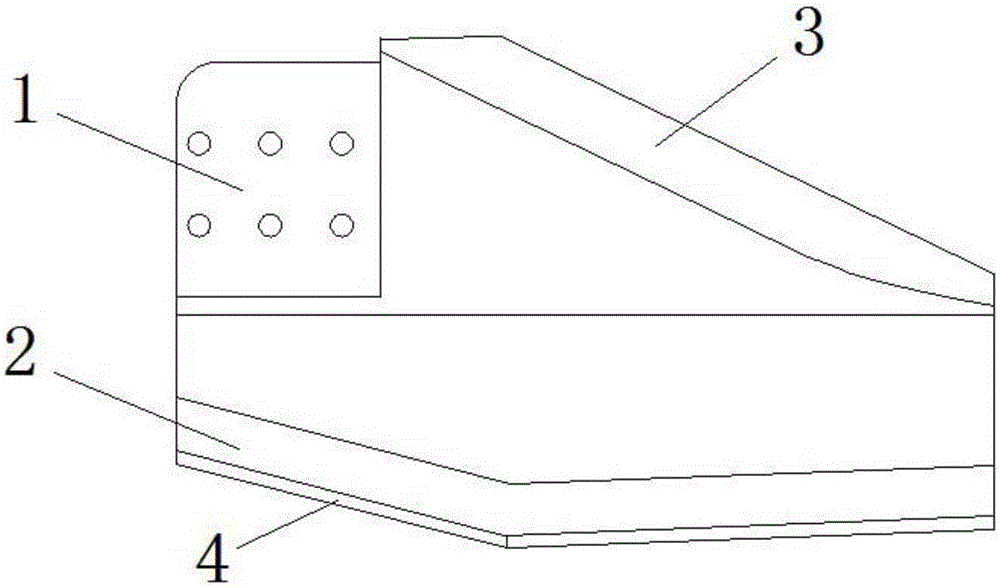
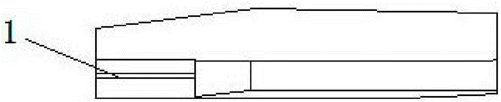
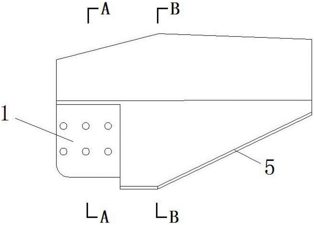
[0031] see Figure 1 to Figure 5 , the inverted long-angle arc-shaped swirl anti-corrosion blade of the present embodiment includes a steel frame 1 based on the shape of the blade and an anti-corrosion material formed by wrapping the steel frame (the steel frame 1 and the anti-corrosion material are prior art, and will not be repeated here. Repeat), the blade is an arc-shaped blade with convex and concave arc surfaces on the upper and lower sides respectively, and one side ( figure 1 Middle is the lower side, figure 2 The middle is the upper side) is composed of two angle lines with similar length, and the other side ( figure 1 Middle is the upper side, figure 2 The middle is the lower side) is composed of a long and a short angled line. It can be seen from the figure that the upper convex surfaces on both sides of the arc-shaped blade are long chamfer 2 and long chamfer 3, and the long chamfer 2 and long chamfer 3 together with the lower side 4 and the lower side 5 close...

Embodiment 2

[0033] see Figure 6 to Figure 7 , the inverted long-angle arc-shaped swirl anti-corrosion stirring paddle of the present embodiment includes a stirring shaft 6, a hub 7 and a paddle 8; as can be seen from the figure, the stirring paddle of the present embodiment is a single-layer three paddle, and the paddle 8 The shape and features are the same as the paddle described in Example 1. The steel frame 1 of the paddle 8 is connected with the butt steel plate 9 of the hub through screws; the hub 7 is fixedly connected to the stirring shaft 6, and the butt steel plate 9 is embedded in the milling groove of the hub 7 and welded and fixed; steel plate (not shown in the figure). from Image 6 It can be seen from the figure that the arc-shaped paddle 8 is obliquely installed on the hub 7 of the stirring shaft 6. Looking in the direction of the stirring shaft 6, the upper liquid level is on the left, the lower liquid level is on the right, the upper liquid level is on the upper side, ...

Embodiment 3

[0037] see Figure 8 , The stirring paddle of the present embodiment is a double-layer six paddle, and the shape and characteristics of the paddle 8, the hub 7 and the stirring shaft 6 are the same as those of the second embodiment.

[0038] The stirring paddle of the present embodiment is suitable for the stirring of 120 cubic to 800 cubic compound barrels.


PUM

PropertyMeasurementUnit
Lengthaaaaaaaaaa
Widthaaaaaaaaaa
Thicknessaaaaaaaaaa

Abstract

The invention discloses a chamfer angle arc-shaped swirl anticorrosion blade and a chamfer angle arc-shaped swirl anticorrosion stirring paddle. The upper portion convex surfaces of two side surfaces of the arc-shaped blade are chamfer angles, and the upper portion convex surfaces and the lower portions of right angle approaching edges of the two side surfaces commonly form the upper liquid entrance surface and the lower liquid poking surface of the blade, and the side edge of the upper liquid entrance surface is formed by two angle lines with similar lengths; the root of the convex surface of the arc-shaped blade is a part close to a stirring shaft, the middle and the tail of the convex surface of the arc-shaped blade are parts far from the stirring shaft, and the cross sections of the three parts are arc surfaces formed by circles with different radii; and the root of the concave surface of the arc-shaped blade is a part close to the stirring shaft, the middle and the tail of the concave surface of the arc-shaped blade are parts far from the stirring shaft, and the cross sections of the three parts are arc surfaces formed by circles with different radii. The chamfer angle arc-shaped swirl anticorrosion blade and the chamfer angle arc-shaped swirl anticorrosion stirring paddle, provided by the invention, can widen the flow path stretching force and number-shaped strong swirling force of a stirring blade, and have the advantages of power saving, consumption reduction, yield increase and long service life.

Description

technical field [0001] The invention belongs to the technical field of blades and stirring paddles, and in particular relates to a convex inverted long-angle arc-shaped swirl anti-corrosion blade and an inverted long-angle arc-shaped swirl anti-corrosion stirring paddle with strong invisible extension swirl force. The anti-corrosion stirring paddle is single-layer four paddles double-layer eight paddles or single-layer three paddles double-layer six paddles, which are used for various anti-corrosion stirring in tanks and tanks equipped with mixing paddles. Background technique [0002] Usually, in the electrochemical industry, due to the decline of mineral resource content and the increase of solid-liquid ratio in leaching, the process technology requirements of manganese dioxide, metal manganese, electrolytic copper and electrolytic aluminum industries are continuously improved, in order to adapt to its changeable advanced technology , manganese dioxide, metal manganese, el...

Claims


Application Information

Patent Timeline
IPC IPC(8): B01F15/00
Inventor 李兴国苏金红李佑堂
Owner 李兴国
Why Eureka
Try Eureka