

Continuous casting permanent magnet spiral magnetic field stirrer
A helical magnetic field and stirrer technology, which is applied in the direction of mixer accessories, chemical instruments and methods, mixers, etc., can solve the problems of high design and production costs of hydraulic motors and gear transmission mechanisms, low control precision of axial force and circumferential force, and overall problems of mixers. Complicated structure and other issues, to save materials and maintenance costs, reduce production costs, and achieve significant water-saving effects
Active Publication Date: 2019-08-23
包钢集团电气有限公司
View PDF4 Cites 5 Cited by
- Summary
- Abstract
- Description
- Claims
- Application Information
AI Technical Summary
Problems solved by technology
[0002] From the operating principle of the agitator, it can be seen that the driving device of the motor, the coil production, and the design of the water system directly determine the quality of the downstream products of the agitator, the working efficiency and service life of the agitator itself. At present, various types of agitators have The disadvantages are as follows: 1. The design and production cost of hydraulic motor and gear transmission mechanism is relatively high, and the structure is complex; 2. The control accuracy of axial force and circumferential force is low; 3. Aiming at the characteristics of small liquid core and high viscosity at the end of solidification, strong magnetic field drive is required; 4 .Because the agitator is affected by the radiant heat of the slab at the end of the solidification of the slab, the insulation of the agitator coil is seriously aged and the service life is reduced; 5. Since the agitator must be cooled with a large flow of pure water, the cost of equipment use and maintenance is relatively high; therefore, It is very necessary to design and manufacture a stirrer that eliminates the above various drawbacks
[0003] In addition, some of the current agitators that can generate a spiral magnetic field are realized through its driving structure, resulting in excessive volume, high manufacturing costs, and complex overall structure of the agitator, which is very unfavorable for later maintenance.
Method used
View moreImage
Smart ImageViewing Examples

Examples
Embodiment
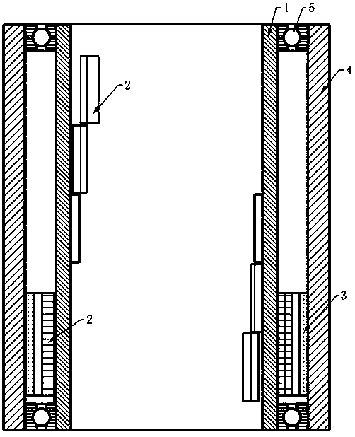
[0035] Such as Figure 5 As shown, in the present invention, the bearing 5 can also be replaced with a roller as a support position when the steel cylinder 1 rotates, and the wheels are installed on the fixed shaft through the fixed handle-type fixed shaft at equal intervals on the edge of the steel cylinder 1. The wheel surface is attached to the inner wall of the shell 4 to form a support for the steel cylinder 1, and ring-shaped baffles are fixed at both ends of the shell. This design forms a relatively open space between the steel cylinder 1 and the shell 4 at both ends. , so the heat dissipation will be improved.
Login to View More PUM
 Abstract
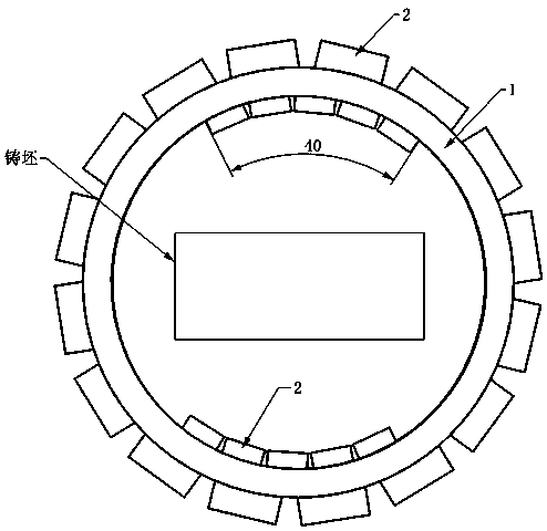
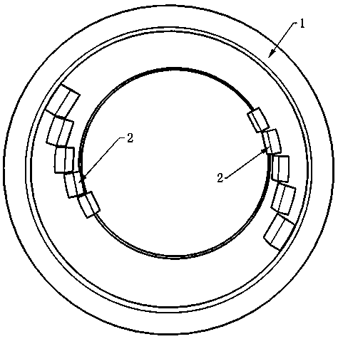
The invention discloses a continuous casting permanent magnet spiral magnetic field stirrer which comprises a steel cylinder, magnetic steel, a stator iron core and a shell. The continuous casting permanent magnet spiral magnetic field stirrer is characterized in that the shell is of a topless bottomless tubbish structure; the steel cylinder is of a topless bottomless tubbish structure; the steelcylinder is sleeved by the shell in a concentric manner; the stator iron core is fixed on the inner wall of the shell; a coil is embedded into the stator iron core to form a stator winding; the magnetic steel is fixed on the outer wall of the steel cylinder in a manner of surrounding the steel cylinder to form a rotor magnetic pole; two pieces of magnetic steel arranged in a spiral line are fixedon the inner wall of the steel cylinder; the two pieces of magnetic steel arranged in the spiral line mutually form an angle of 180 degrees in symmetry with the steel cylinder as a center; an includedangle of 40 degrees is formed by a head block and a tail block of each piece of magnetic steel to form an internal spiral magnetic field; and both ends of the stator iron core are assembled inside the shell through bearings. The stirrer is small in size, light in weight, simple in transmission, flexible to control, stable in performance, low in energy consumption, good in practicability and easyto popularize.
Description
technical field [0001] The invention relates to metallurgical continuous casting equipment, in particular to a continuous casting permanent magnetic spiral magnetic field agitator. Background technique [0002] From the operating principle of the agitator, it can be seen that the driving device of the motor, the coil production, and the design of the water system directly determine the quality of the downstream products of the agitator, the working efficiency and service life of the agitator itself. At present, various types of agitators have The disadvantages are as follows: 1. The design and production cost of hydraulic motor and gear transmission mechanism is relatively high, and the structure is complex; 2. The control accuracy of axial force and circumferential force is low; 3. Aiming at the characteristics of small liquid core and high viscosity at the end of solidification, strong magnetic field drive is required; 4 .Because the agitator is affected by the radiant hea...
Claims
Login to View More Application Information
Patent Timeline
 Patent Type & AuthorityApplications(China)
IPC IPC(8): B01F13/08B01F15/00B01F15/06
CPCB01F33/451B01F35/3204B01F2035/98B01F35/92B01F2101/26
Inventor裴海军周盛荣王青崔婷婷高洋盛世和常亮王玉倩王广兰
Owner包钢集团电气有限公司