
Distributed limited time tracking control method for formation-flying satellites

A tracking control, limited time technology, applied in the field of tracking control, can solve the problems of limited communication, difficult to achieve, and difficult to achieve communication topology.

Active Publication Date: 2015-12-09
HARBIN INST OF TECH
View PDF5 Cites 55 Cited by
  • Summary
  • Abstract
  • Description
  • Claims
  • Application Information

AI Technical Summary

Problems solved by technology

However, the control algorithm needs to use the upper bound information of the navigator control input, which is difficult to achieve in practical applications.
[0007] Min.H. et al. studied the consistency problem of multi-Euler-Lagrange systems with model parameter uncertainty under the directed communication topology, and proposed an adaptive consensus control algorithm, but this algorithm assumes that the communication topology is balanced It is proposed under the premise that in actual engineering applications, such a communication topology is difficult to realize due to the limited communication

Method used


Image

  • Distributed limited time tracking control method for formation-flying satellites
  • Distributed limited time tracking control method for formation-flying satellites
  • Distributed limited time tracking control method for formation-flying satellites

Examples


specific Embodiment approach 1

[0091] Specific Embodiments 1. A distributed finite time tracking control method for formation satellites described in this embodiment is carried out according to the following steps:

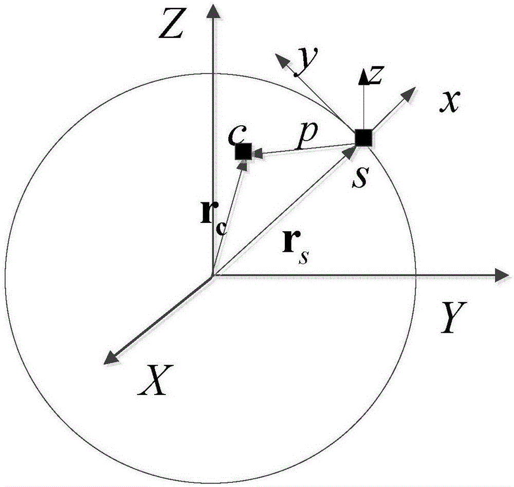
[0092] 1. Establish a binary star relative motion dynamics model:

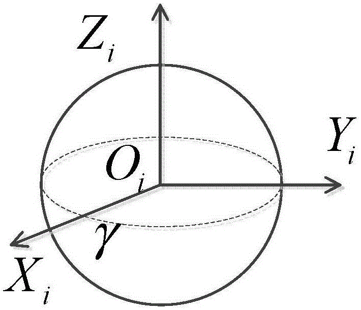
[0093] 1.1. Define the geocentric inertial coordinate system: take the center of the earth as the origin, O i x i The axis is along the intersection of the Earth's equatorial plane and the ecliptic plane, pointing to the vernal equinox γ, O i Z i Axis points to North Pole, O i Y i axis forms a right-handed system with the other two axes, such as figure 1 shown;

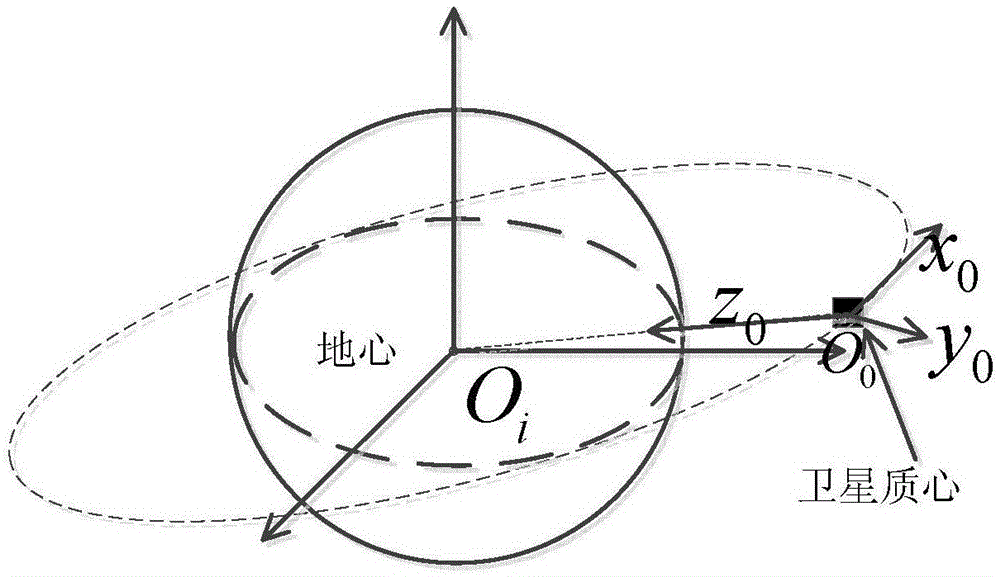
[0094] 1.2. Define the orbital coordinate system: take the center of mass of the satellite as the origin, O o Z o The axis points from the center of mass of the satellite to the direction of the center of the earth, O o x o axis in the orbital plane with O o Z o The axis is vertical, along the direction of satellite flight, O o Y o axis is perpendicular t...

specific Embodiment approach 2

[0128] Specific Embodiment 2. This embodiment is a further description of the distributed finite-time tracking control method of a formation satellite described in the specific embodiment 1. The relative motion dynamics model of the formation satellite relative to the reference point established in step 2 And the distributed finite-time tracking control law designed in step 3 satisfies the following conditions:

[0129] (1), generalized interference d oi Unknown but bounded, satisfy ||d oi || 2 ≤d max max is an unknown, bounded constant, ||·|| 2 Indicates seeking 2-norm;

[0130] (2), there is a normal number and make 0 m ‾ ≤ m i n [ | m o 1 | , ... , | m o ...


PUM


Abstract

The invention relates to a tracking control method and especially relates to a distributed limited time tracking control method for formation-flying satellites. The invention aims at solving problems that the communication among formation-flying satellites is limited in a conventional formation-flying satellite control method, the control input upper limit information of a pilotage satellite is difficult to obtain, the inevitable perturbation of all satellites in a system cannot be considered, and the formation is longer in time. The method comprises the following steps: 1, building a double-satellite relative movement dynamic model; 2, building a relative dynamic model of the formation-flying satellites relative to a reference point; 3, designing a distributed limited time tracking control rule. The method solves a problem that the communication among formation-flying satellites is limited in the conventional satellite formation control method, considers the inevitable perturbation of all satellites in the system, and can complete the formation in a shorter time. The method can be used in the field of tracking control.

Description

technical field [0001] The invention relates to a tracking control method, in particular to a distributed limited-time tracking control method for formation satellites. Background technique [0002] In recent years, the rapid development of new energy, new materials, and communication technologies has further broadened the application space of satellite formation flight systems based on small satellite technology. In the satellite formation system, each formation satellite forms a specific formation configuration based on the reference point, and flies around the earth with the same orbital period while maintaining the formation. If each formation satellite fulfills a function, the entire formation system can complete more complex space tasks through the cooperation of each formation satellite. Compared with a single satellite, the formation system has stronger fault tolerance. When a satellite in a formation fails, it will not lead to the failure of the entire space missio...

Claims


Application Information

Patent Timeline
IPC IPC(8): G05D1/10B64G1/24G06F17/50
Inventor 王俊孙延超李传江常雅杰吕腾马广富
Owner HARBIN INST OF TECH
Learn More