Epoxy resin cast coil for dry-type transformer

A technology of dry-type transformer and epoxy resin, which is applied in the direction of transformer/inductor coil/winding/connection, etc., and can solve problems affecting the service life of the transformer

Inactive Publication Date: 2015-12-09
宁波甬嘉变压器有限公司
View PDF9 Cites 2 Cited by
  • Summary
  • Abstract
  • Description
  • Claims
  • Application Information

AI Technical Summary

Problems solved by technology

However, this type of mesh cloth material is formed by weaving glass fiber tapes and impregnating a solvent-containing insulating varnish after dr

Method used


Image

  • Epoxy resin cast coil for dry-type transformer
  • Epoxy resin cast coil for dry-type transformer
  • Epoxy resin cast coil for dry-type transformer

Examples


Embodiment Construction

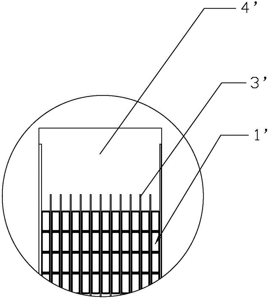
[0021] Combine below Figure 4 , Figure 5 with Image 6 The present invention is described in further detail.

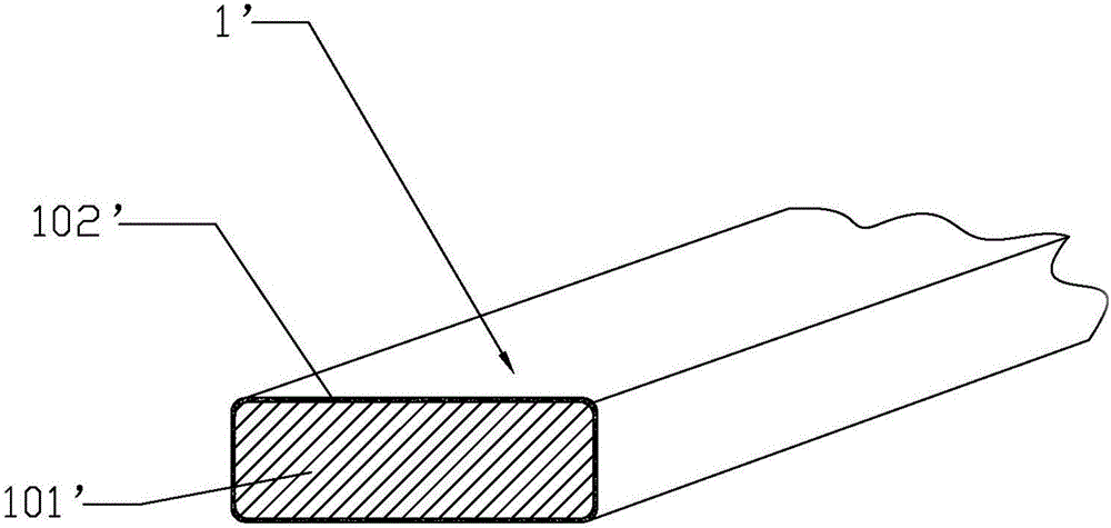
[0022] as attached Figure 4 , the present invention is an epoxy resin cast coil for dry-type transformers, which includes a coil body 2 that is formed by winding a wire 1 into a multi-layer structure and pouring epoxy resin 4; as attached Image 6 As shown, the wire 1 includes a conductive body 101 and a glass fiber strip 102 wound and fixed on the outer peripheral surface of the conductive body 101 in a helical form; the adjacent glass fiber strips 102 on the conductive body 101 are arranged at intervals; wherein the adjacent glass fibers The separation distance between the strips 102 is 2-3mm. Among them, the glass fiber strips 102 are wound and fixed on the conductive body 101 in a helical form, and the distance between adjacent glass fiber strips 102 is 2-3mm. The finished coil 2 for the dry-type transformer, when performing the casting epoxy resin process...


PUM

PropertyMeasurementUnit
Diameteraaaaaaaaaa

Abstract

The invention discloses an epoxy resin cast coil for a dry-type transformer. The epoxy resin cast coil comprises a coil body (2) which is formed by casting a multilayered structure wound by a wire (1) with epoxy resin (4), wherein the wire (1) comprises a conductive body (101) and glass fiber ribbons (102) spirally wound and fixed on the peripheral surface of the conductive body (101); the adjacent glass fiber ribbons (102) on the conductive body (101) are arranged at intervals. The epoxy resin cast coil has the advantage that the transformer adopting the coil does not partially discharge after being energized for operation.

Description

technical field [0001] The invention relates to an epoxy resin casting coil for a dry-type transformer. Background technique [0002] as attached figure 1 , attached figure 2 and attached image 3 As shown, at present, the epoxy resin-cast coil 2' on the dry-type transformer (the wire is wound and poured through epoxy resin), the wire 1' used in this type of coil, the specific structure is the outer surface of the wire body 101' Wrapping the insulating layer 102', the form of setting the insulating layer is mainly insulating varnish-wrapped insulation or film-wrapped wire-wrapped insulation. Since the insulating material used in the above two types of insulating layers is mainly polyester insulating varnish, this type of insulation The varnish contains volatile solvents, and the coils wound with such wires tend to generate bubbles inside the coil due to the volatilization of the solvent in the insulating varnish during the epoxy casting process (because the temperature d...

Claims


Application Information

Patent Timeline
IPC IPC(8): H01F27/28H01F27/32
Inventor 包志明李莉
Owner 宁波甬嘉变压器有限公司
Why Eureka
Try Eureka