ultra-small dielectric resonator

A dielectric resonator, dielectric resonance technology, applied in resonators, waveguide devices, circuits, etc., can solve the problems of increased product scrap rate, heavy product quality, poor heat dissipation performance, etc. and the effect of quality reduction and reliable product performance

Active Publication Date: 2018-09-25
武汉凡谷陶瓷材料有限公司
View PDF11 Cites 0 Cited by
  • Summary
  • Abstract
  • Description
  • Claims
  • Application Information

AI Technical Summary

Problems solved by technology

[0003] When the operating frequency of the filter composed of TM mode dielectric resonators is increased to above 2 GHz, the wall thickness of the cylindrical dielectric resonator rod becomes thinner, which causes the dielectric resonator rod to be easily cracking, the product scrap rate increases significantly; the axial center of the dielectric resonator rod opens a hole, and the Q value of the resonator decreases, resulting in extremely limited performance improvement space; the operating frequency of the resonator increases, and its volume becomes smaller. The dense arrangement of coupling screws increases the difficulty of device debugging; at present, the TM mode dielectric resonator is fixed by axial pressure. After the wall thickness of the cylindrical dielectric resonator rod becomes thinner, the pressure it can withstand is limited. Very fragile
In summary, the existing TM mode dielectric resonators cannot be popularized and used in filter products with operating frequencies exceeding 2 GHz due to various technical bottlenecks
[0004] Since the dielectric waveguide filter is entirely made of microwave dielectric ceramics, the product molding process is complicated, the manufacturing cost is high, and the heat dissipation performance is poor, and the product quality is heavy under the same performance and volume, and there is no possibility of mass use at present.

Method used


Image

  • ultra-small dielectric resonator
  • ultra-small dielectric resonator
  • ultra-small dielectric resonator

Examples


Embodiment Construction

[0024] The present invention will be described in further detail below in conjunction with accompanying drawing and specific embodiment, but described specific embodiment is only for explaining the present invention, does not limit protection scope of the present invention:

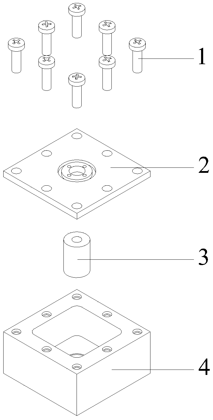
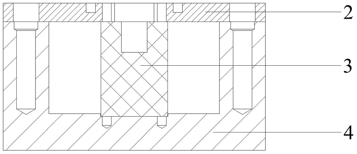
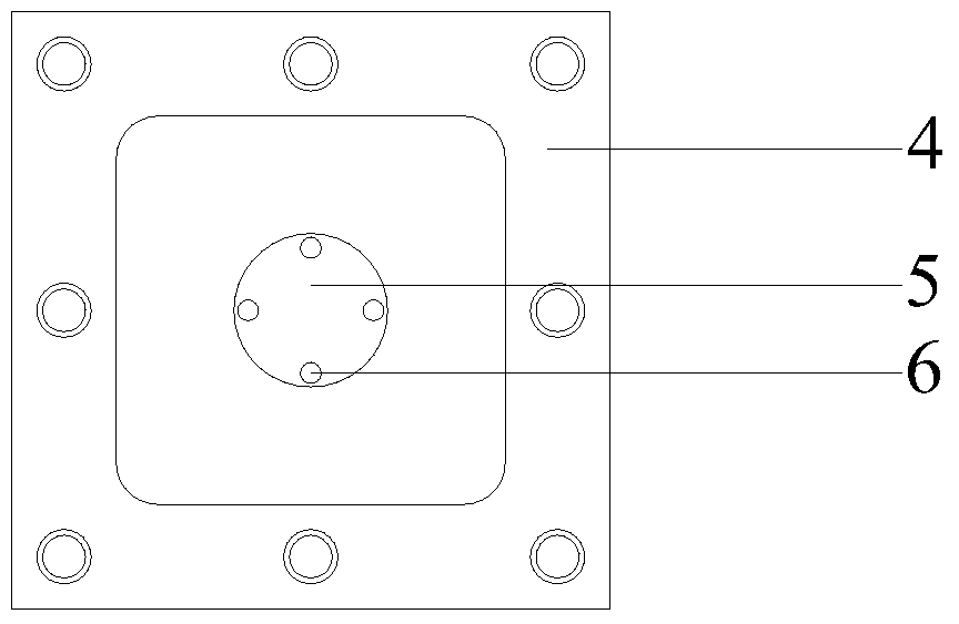
[0025] Such as figure 1 and figure 2 As shown, this embodiment relates to an ultra-small dielectric resonator, including a cover plate 2, a dielectric resonator rod 3 and a metal cavity 4 with a circular shallow hole 5 at the bottom, and the cover plate 2 is fixed on the metal cavity 4 by an assembly screw 1 Above, the dielectric resonator rod 3 is positioned and fixed at the bottom of the metal cavity 4 through the circular shallow hole 5 at the bottom of the metal cavity 4 .

[0026] The outer surface of the cover plate 2 is provided with an annular shallow groove 8 coaxial with the dielectric resonance rod 3, and the inner diameter of the annular shallow groove 8 is equal to the outer diameter of the...


PUM

PropertyMeasurementUnit
diameteraaaaaaaaaa
thicknessaaaaaaaaaa

Abstract

The invention discloses an ultra-small dielectric resonator, which comprises a cover plate, a dielectric resonance rod and a metal cavity with a circular shallow hole at the bottom, the dielectric resonance rod is positioned and fixed at the bottom of the metal cavity through the circular shallow hole at the bottom of the metal cavity, and the cover plate Located on the top of the metal cavity, the dielectric resonator rod is a cylindrical microwave dielectric ceramic with a circular blind hole at the upper end, and its upper and lower end surfaces are in close contact with the metal cover plate and the positioning shallow hole at the bottom of the metal cavity respectively. The present invention uses microwave dielectric ceramics to make a cylindrical dielectric resonator rod with a blind hole at the upper end, which solves the problem of low production pass-through rate, limited space for product performance improvement, and difficulty in product debugging of the resonator rod of the TM mode dielectric resonator with an operating frequency greater than 2 GHz. At the same time, the product of the present invention has simple production process, low manufacturing cost, strong product market competitiveness and broad application prospects.

Description

technical field [0001] The invention relates to a passive antenna feeder device in the field of wireless network communication, in particular to an ultra-small dielectric resonator. Background technique [0002] For a long time, filters have played an extremely important role in the processing of electronic signals. It has the function of filtering signals of used frequencies and suppressing interference signals. With the rapid development of microwave wireless communication, miniaturized base stations have become the mainstream, and more and more stringent requirements have been placed on the volume of filters. Filters composed of traditional metal coaxial resonators can no longer meet these requirements. At present, filters composed of TM mode dielectric resonators and dielectric waveguide filters, which are mainstream in the industry, have various practical difficulties in actual production and application, and are not suitable for Mass industrial production, mainly in: ...

Claims


Application Information

Patent Timeline
Patent Type & Authority Patents(China)
IPC IPC(8): H01P7/10
Inventor 孟庆南钟伟刚
Owner 武汉凡谷陶瓷材料有限公司
Why Eureka
Try Eureka