Novel high-gain printed quasi-yagi antenna

A high-gain, quasi-Yagi technology, applied in the direction of antennas, electrical components, etc., can solve the problem of small gain of quasi-Yagi antennas, and achieve the effect of good matching, high gain, and good radiation enhancement effect

Inactive Publication Date: 2015-12-09
HARBIN INST OF TECH
View PDF1 Cites 4 Cited by
  • Summary
  • Abstract
  • Description
  • Claims
  • Application Information

AI Technical Summary

Problems solved by technology

[0003] In order to solve the problem that the printed quasi-Yagi antenna of the existing single director has a smal

Method used


Image

  • Novel high-gain printed quasi-yagi antenna
  • Novel high-gain printed quasi-yagi antenna

Examples


specific Embodiment approach 1

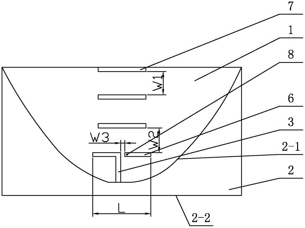
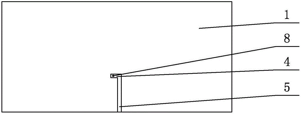
[0007] Specific implementation mode one: combine figure 1 and figure 2 To illustrate this embodiment, a new type of high-gain printed quasi-Yagi antenna described in this embodiment includes a dielectric substrate 1, a reflector 2, a front elongated feeder 3, a rear rectangular feeder 4, a rear elongated feeder 5, two The source oscillator arm 6 and the three guide oscillators 7, the reflector 2 is printed on the lower part of the front of the dielectric substrate 1, the reflector 2 is a closed metal layer composed of a concave parabolic side 2-1 and a straight line side 2-2, and The straight side 2-2 of the reflector 2 coincides with the bottom edge of the front of the dielectric substrate 1, and the three guiding vibrators 7 are printed sequentially on the upper part of the front of the dielectric substrate 1 from top to bottom, and the two active vibrator arms 6 are in the shape of a line Printed on the middle of the front surface of the dielectric substrate 1, two active...

specific Embodiment approach 2

[0009] Specific implementation mode two: combination figure 1 and figure 2 Describe this embodiment, the length of the dielectric substrate 1 of a novel high-gain printed quasi-Yagi antenna described in this embodiment is 180 mm, the width of the dielectric substrate 1 is 100 mm, and the thickness of the dielectric substrate 1 is 1.6 mm.

[0010] The technical effect of this embodiment is that: with such an arrangement, the impedance and radiation characteristics of the antenna are good. Other components and connections are the same as those in the first embodiment.

specific Embodiment approach 3

[0011] Specific implementation mode three: combination figure 1 and figure 2 To illustrate this embodiment, the length of the straight side 2-2 of the reflector 2 of a novel high-gain printed quasi-Yagi antenna described in this embodiment is 180 mm.

[0012] The technical effect of this embodiment is that: with such an arrangement, the impedance and radiation characteristics of the antenna are good. Other components and connections are the same as those in the first embodiment.


PUM

PropertyMeasurementUnit
Lengthaaaaaaaaaa
Widthaaaaaaaaaa
Thicknessaaaaaaaaaa

Abstract

The invention discloses a novel high-gain printed quasi-yagi antenna, relates to a printed quasi-yagi antenna, in particular to a novel high-gain printed quasi-yagi antenna, and aims at solving the problems that the printed quasi-yagi antenna of an existing single director is relatively small in grain and cannot meet the reality requirement. The novel high-gain printed quasi-yagi antenna comprises a dielectric substrate, a reflector, a front strip feeder, a back rectangular feeder, a back strip feeder, two active oscillator arms and three director dipoles, wherein the reflector is printed at the lower part of the front surface of the dielectric substrate, and is an enclosed metal layer which is composed of a concave parabola side and a straight line side; the straight line side of the reflector overlaps with the bottom side of the front surface of the dielectric substrate; the three director dipoles are sequentially printed at the upper part of the front surface of the dielectric substrate from top to bottom; two active oscillator arms are printed in the middle of the front surface of the dielectric substrate in a line form; the two active oscillator arms form an active oscillator; and the right end of the active oscillator arm at the left side is connected with the middle part of the parabola side of the reflector through the front strip feeder. The novel high-gain printed quasi-yagi antenna belongs to the field of wireless communication.

Description

technical field [0001] The invention relates to a printed quasi-Yagi antenna, in particular to a novel high-gain printed quasi-Yagi antenna, which belongs to the field of wireless communication. Background technique [0002] In a communication system, a device used to transmit or receive electromagnetic waves is called an antenna, and the antenna can effectively convert the energy of a current or guided wave into the energy of an electromagnetic wave of the same frequency, or effectively convert the energy of an electromagnetic wave into a current of the same frequency or guided wave energy. The directional antenna, also known as the Yagi antenna, was invented by Yagi Hideji and Uda Taro of Tohoku University in Japan in 1928. It has a history of nearly a century. Widely used in radar systems and radio communications. Three pairs of oscillators are the main features of a typical Yagi antenna, and the entire antenna structure is similar to a "King" shape. Among the three pa...

Claims


Application Information

Patent Timeline
IPC IPC(8): H01Q19/30
Inventor 宗华谷海川张庆鑫赵志华
Owner HARBIN INST OF TECH
Why Eureka
Try Eureka