Tooth slot structure of high-power-density permanent magnet brushless motor used for space manipulator

A permanent magnet brushless motor, high power density technology, applied in the field of motors, can solve the problem of reducing volume, achieve the effect of reducing the overall length, simple structure, and reduced complex procedures

Inactive Publication Date: 2015-12-09
HARBIN INST OF TECH
View PDF6 Cites 5 Cited by
  • Summary
  • Abstract
  • Description
  • Claims
  • Application Information

AI Technical Summary

Problems solved by technology

[0005] The purpose of the present invention is to solve the problem that the existing space manipulator motor is equipped with redundant design and cannot take into account the problem of volume reduction, and provides a cogging structure of high power density permanent magnet brushless motor for space manipulator

Method used


Image

  • Tooth slot structure of high-power-density permanent magnet brushless motor used for space manipulator
  • Tooth slot structure of high-power-density permanent magnet brushless motor used for space manipulator
  • Tooth slot structure of high-power-density permanent magnet brushless motor used for space manipulator

Examples


specific Embodiment approach 1

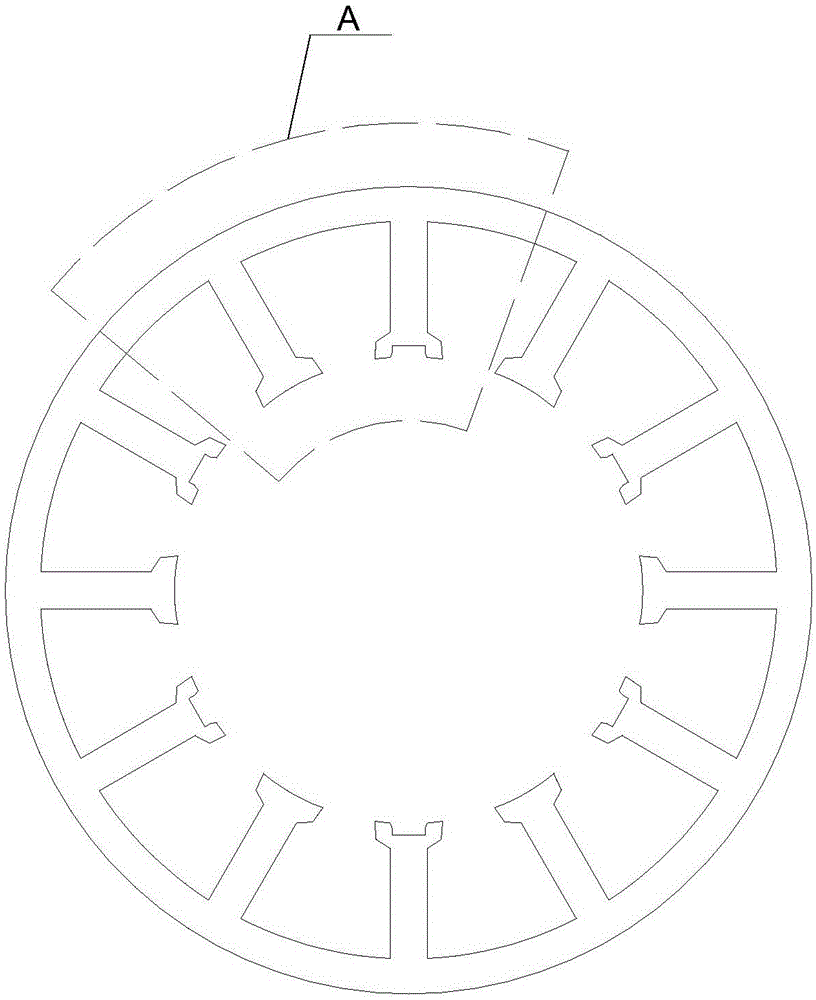
[0012] Specific implementation mode one: the following combination Figure 1 to Figure 3 Describe this embodiment, the cogging structure of the high power density permanent magnet brushless motor for the space robot arm described in this embodiment, the inner surface of the stator of the motor is arranged along the circumference of p pairs of stator teeth, and every two adjacent stator teeth Stator tooth slots are formed between the pole shoes, and the stator tooth slots are narrow outside and wide inside; there are Hall element embedded slots at the tooth crowns of the p stator teeth, and the slots face the direction of the center of the circle ; The p stator teeth with Hall element embedded slots are arranged alternately with the remaining p stator teeth;

[0013] p is a positive integer greater than or equal to 2.

[0014] The motor involved in this embodiment includes a stator and a rotor. The stator is arranged outside the rotor. The rotor adopts a hollow disc structure....

specific Embodiment approach 2

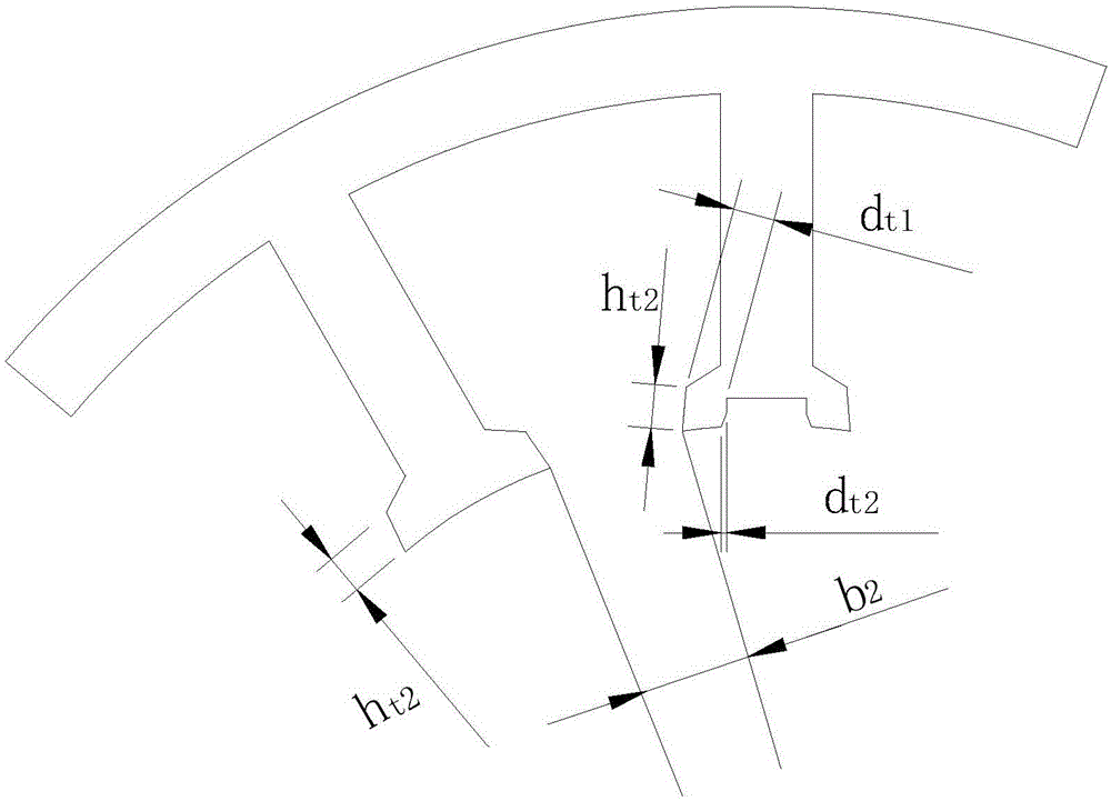
[0017] Embodiment 2: In this embodiment, Embodiment 1 is further described. The Hall element embedding groove is in the shape of a bell mouth, and the outer edge of the groove is the position of the horn opening.

[0018] Increase the width of the notch, i.e. increase d t1 , so that the opening width at the outer edge of the notch becomes larger, forming a bell mouth shape, so as to prevent the saturation of the magnetic circuit, make the magnetic density distribution as uniform as possible, and reduce the harmonic component in the current.

specific Embodiment approach 3

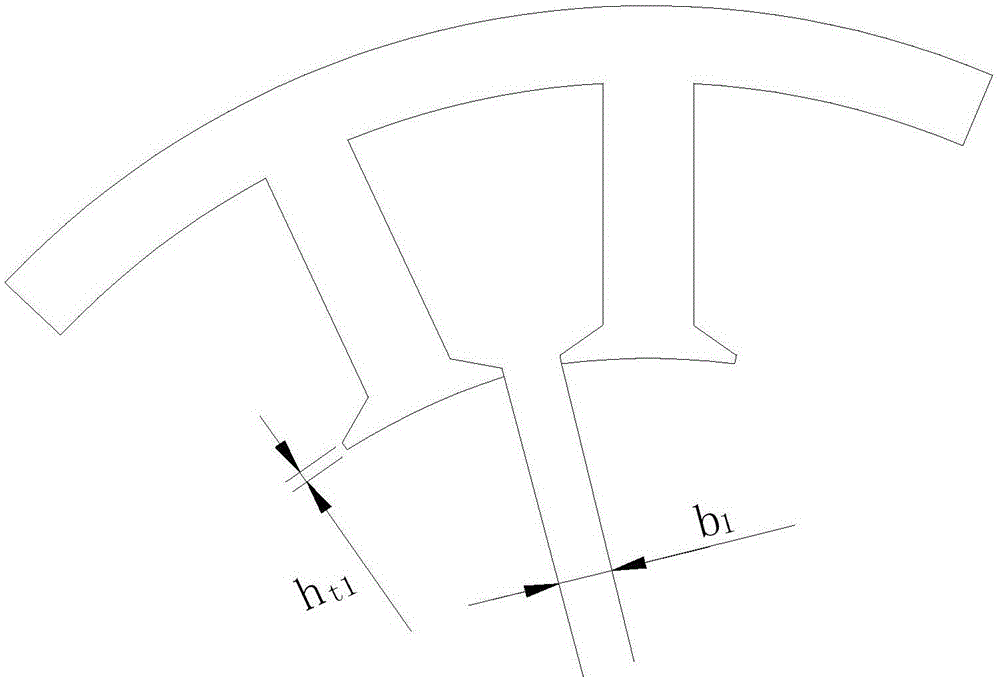
[0019] Embodiment 3: In this embodiment, Embodiment 1 or Embodiment 2 is further described. The ratio of the radial thickness of the notches of the stator teeth to the radial height of the stator teeth is 0.2-0.3.

[0020] figure 1 The stator tooth structure of a conventional motor is shown, and the radial thickness of the stator slots is b 1 , accounting for 0.1 to 0.15 of the radial height of the stator teeth, and the radial thickness h of the stator tooth notch in this embodiment t2 It is thicker than the radial thickness of the slot of the stator tooth of the traditional motor, so as to better insert the Hall element.


PUM


Abstract

The invention provides a tooth slot structure of a high-power-density permanent magnet brushless motor used for a space manipulator, belongs to the technical field of motors, and aims at solving problems that existing motors used for the space manipulator cannot consider reduction of the size under the condition of equipping of redundancy design. The scheme is that p pairs of stator teeth are arranged on the surface of the internal circle of a motor stator along circumference. A stator tooth slot port is formed between the pole shoes of every two adjacent stator teeth, and the stator tooth slot port has a structure of which the external part is narrow and the internal part is wide. Hall element embedding slots are arranged at the tooth crowns of the p stator teeth, and the slot ports face direction of the center of the circle. The p stator teeth with the Hall element embedding slots and the rest p stator teeth are arranged in a staggered way, and p is a positive integer greater than or equal to 2. Hall elements are embedded in the motor teeth so as to reduce the axial size of the motor. A special tooth type and slot type structure is adopted so as to ensure relatively small positioning moment and moment fluctuation.

Description

technical field [0001] The invention relates to a special tooth-shaped structure of a high power density permanent magnet brushless motor for a space manipulator, belonging to the technical field of motors. Background technique [0002] The space robotic arm is an important device necessary for space engineering, assisting astronauts to complete high-precision transportation and maintenance work. The design requirements of the mechanical arm are high strength, high reliability, flexible work and light volume and weight as possible. Electromagnetic devices are essential in the manipulator drive system. Compared with hydraulic drive and other common drive methods for ground manipulators, electromagnetic drive has great advantages in the space field. Therefore, as far as the current development of the space field is concerned, other countries with advanced space science and technology have adopted electromagnetic drive methods to solve the drive problem of space manipulators....

Claims


Application Information

Patent Timeline
Patent Type & Authority Applications(China)
IPC IPC(8): H02K29/08
Inventor 尚静邹继斌胡建辉王骞赵猛刘雪缘
Owner HARBIN INST OF TECH
Why Eureka
Try Eureka