Method for filling a microfluidic device using a dispensing system and corresponding test system

A technology of microfluidic device and test system, which is applied in measurement devices, fluid controllers, chemical instruments and methods, etc., can solve problems such as unfavorable bedside systems, and achieve the effect of rapid evaluation

Active Publication Date: 2015-12-09
吉斯彼德生物技术有限公司
View PDF11 Cites 3 Cited by
  • Summary
  • Abstract
  • Description
  • Claims
  • Application Information

AI Technical Summary

Problems solved by technology

But the arrangement of its own liquid circulation fo...

Method used


Image

  • Method for filling a microfluidic device using a dispensing system and corresponding test system
  • Method for filling a microfluidic device using a dispensing system and corresponding test system
  • Method for filling a microfluidic device using a dispensing system and corresponding test system

Examples


Embodiment Construction

[0057] First of all, it should be noted that in the differently described embodiments, the same parts are provided with the same reference signs or the same component designations, and the disclosure contained in the entire description can be applied to the same reference signs or the same component designations. parts. Position specifications selected in the description, such as top, bottom, side, etc., also refer to the directly illustrated and described figures and, in the event of a change in position, apply sensibly to the new position. In addition, individual features or combinations of features from the various exemplary embodiments shown and described can also form independent, inventive or inventive solutions in themselves.

[0058] All data of numerical ranges in this specification are to be understood in such a way that these numerical ranges also include any and all subranges of these numerical ranges together, for example data 1 to 10 are to be understood in such ...


PUM


Abstract

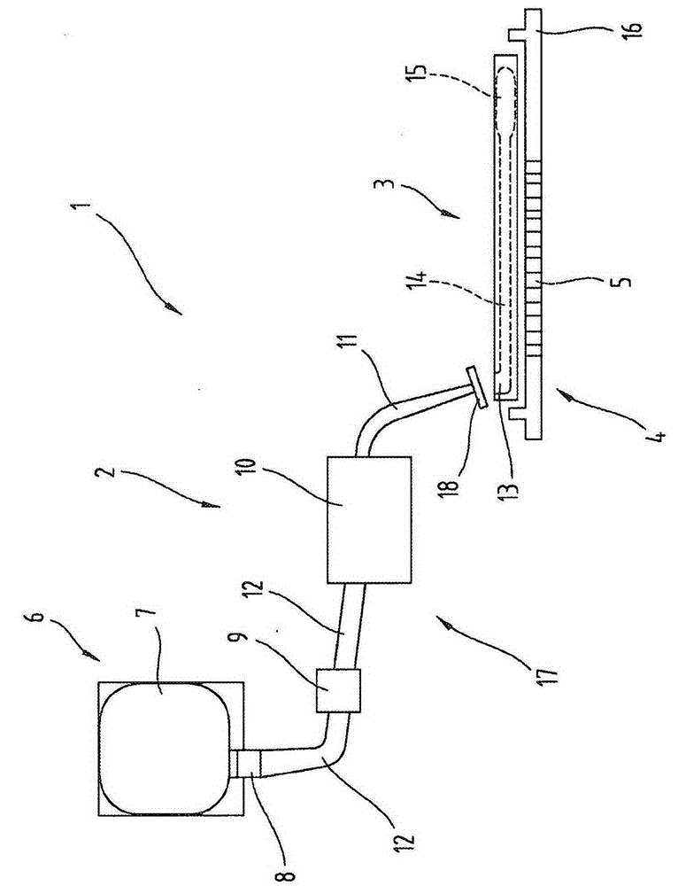
The invention relates to a method for filling a microfluidic device (3) using a dispensing system (2), said method comprising at least the following steps: (a) transporting the solution from the container (6) to the sample application opening (13) of the microfluidic device (3) via the nozzle (11) of the dispensing system (2) using a micropump (10); (b) further transporting the solution into the measuring region of the microfluidic channel (14) of the microfluidic device (3); (c) measuring a light signal in the measuring region of the microfluidic device (3) using at least one photosensitive sensor (4) with a plurality of photodetectors (5); and (d) deactivating the micropump (10) if the light signal is detected and/or if the light signal changes.

Description

technical field [0001] The invention relates to a method for filling a nozzle of a dispensing system of a testing system comprising a dispensing system, a microfluidic device and at least one photosensitive sensor with a plurality of photodetectors, as well as a testing system. Background technique [0002] Many point-of-care testing systems in in vitro diagnostics require manual infusion of different solutions into sample vessels. For example, WO2012 / 080339A1 discloses a measuring instrument, in which three different reagents in a volume range of 10 μl need to be manually and sequentially dropped in during the test. The disadvantage of this manual instillation is that the hands are used for a long time when the test is done and the working capacity is restricted. In addition, manual instillation hides a certain risk of producing erroneous results due to little robustness and reproducibility. Furthermore, WO 2012 / 080339 A1 also describes a discharge device for reagents, wh...

Claims


Application Information

Patent Timeline
IPC IPC(8): B01L3/00F04B19/00G01N21/11G01N21/76
CPCF04B19/006B01L3/0293B01L3/502715B01L2200/0642B01L2200/14B01L2300/0645B01L2300/0809B01L2300/0851B01L2300/0864B01L2400/0487G01N21/11G01N21/76G01N35/10G01N2021/0346G01N2035/00158B01L3/00G01N35/1009B01L3/5027B01L2200/027B01L3/50273B01L2200/0689B01L2200/10B01L2300/0609B01L2300/0654B01L2300/123B01L2400/0605G01N1/28G01N2201/02
Inventor O·米勒德尔M·索纳雷特内尔
Owner 吉斯彼德生物技术有限公司
Why Eureka
Try Eureka