Bone cement stirring and injecting system

A technology of bone cement and agitator, which is applied in the field of medical devices, can solve problems such as difficulty in operation, potential safety hazards, and easy solidification of bone cement, so as to avoid the invasion of radiation, improve operation efficiency, and save operation time.

Active Publication Date: 2015-12-16
SUZHOU & SCI & TECH DEV
View PDF8 Cites 14 Cited by
  • Summary
  • Abstract
  • Description
  • Claims
  • Application Information

AI Technical Summary

Problems solved by technology

However, the existing bone cement mixer and injection system are two parts, the bone cement needs to be stirred by the bone cement mixer, and then passed into the injection system, so the operation process is more complicated; moreover, the bone cement is easy to solidify , when the time control is not good, the bone cement will solidify before it is injected into the diseased vertebral body from the injection system, making it difficult to perform the operation
[0004] In addition, due to the limited length of the bone cement outlet tube of the existing bolus injection system, doctors are exposed to a large amount of radiation during the operation of the bolus injection system in the ward. Although protective plates can be used for protection, there are still certain potential safety hazards

Method used


Image

  • Bone cement stirring and injecting system
  • Bone cement stirring and injecting system
  • Bone cement stirring and injecting system

Examples


Embodiment Construction

[0040] The present invention will be further described below in conjunction with the accompanying drawings and embodiments.

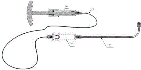
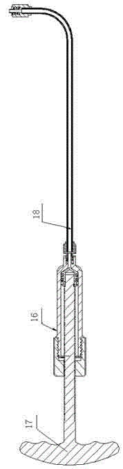
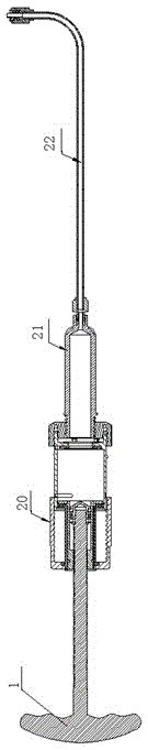
[0041] figure 2 It is the overall structure diagram of the bone cement mixing and injecting system, the system is mainly composed of the screw handle 1, the bone cement mixer 20, the bone cement injection cylinder 21 and the bone cement outlet tube 22; the screw handle 1 and the bone cement mixer 20 are assembled Such as Figure 3-4 as shown, Figure 4 yes image 3 The local enlarged view of the shell assembly 6 and the main container 12 are fixedly connected by multi-threads, the stirring channel part 3 is arranged inside the shell assembly 6, the shell assembly 6 is fixedly connected with the stirring channel part 3, and the stirring movable part 5 is arranged inside the stirring channel part 3, The stirring movable part 5 is slidingly connected with the stirring channel part 3, and an O-ring 4 is set between the stirring movable part 5 and the st...


PUM

PropertyMeasurementUnit
lengthaaaaaaaaaa

Abstract

The invention relates to a bone cement stirring and injecting system. The bone cement stirring and injecting system mainly comprises a spiral handle, a bone cement stirrer, a bone cement injection cylinder and a bone cement outlet pipe, wherein a stirring channel component is arranged in a housing component; a stirring movable part is arranged in the stirring channel component and connected with the stirring channel component in a sliding manner; a spiral handle positioning ring is arranged on the spiral handle; the lower end of the spiral handle is fixedly connected with a piston; the piston is in close connection with the stirring movable part; a blade is fixedly connected to the lower end of the stirring movable part; an injection outlet component is arranged in a main container; an outlet plane sealing part is arranged at the outlet of the main container; and stirrer connecting interfaces are arranged at the lower end of the main container and used for being connected with the bone cement stirrer and the bone cement injection cylinder. The bone cement stirring and injecting system can quickly inject bone cement into a diseased vertebral body, and avoids the phenomenon that solidification occurs when bone cement is not injected into the diseased vertebral body.

Description

technical field [0001] The invention relates to the field of medical devices, in particular to a bone cement mixing and injecting system used in vertebral body balloon dilatation and plastic surgery. Background technique [0002] Balloon vertebroplasty is a minimally invasive spinal surgery, mainly used in the treatment of vertebral compression fractures, which is the most common complication in patients with osteoporosis, causing local pain and mobility impairment In severe cases, it can also lead to paralysis of the lower limbs. Balloon dilatation of the vertebral body first expands the height of the damaged vertebral body through balloon expansion, and then injects bone cement and other fillers into the diseased vertebral body for filling, thereby enhancing the strength and stability of the diseased vertebral body and enabling recovery. The posterior vertebral body will no longer be compressed and deformed. [0003] Common bolus injection systems in the prior art such a...

Claims


Application Information

Patent Timeline
Patent Type & Authority Applications(China)
IPC IPC(8): A61B17/88B01F13/00
CPCA61B17/00234A61B17/8802A61B17/8805A61B2017/564B01F33/50112B01F33/836B01F2101/20
Inventor 陆强
Owner SUZHOU & SCI & TECH DEV
Why Eureka
Try Eureka