Method and device for improving energy efficiency of molten iron storage and transportation

A molten iron and energy efficiency technology, applied in the field of metallurgy, can solve the problems of large surface heat loss of molten iron, lack of heat preservation measures in molten iron, energy loss of molten iron, etc., so as to reduce the loss of molten iron, improve metal yield, and reduce the effect of dissipation.

Active Publication Date: 2019-11-05
WISDRI ENG & RES INC LTD
View PDF11 Cites 0 Cited by
  • Summary
  • Abstract
  • Description
  • Claims
  • Application Information

AI Technical Summary

Problems solved by technology

[0003] Under the existing technology, the molten iron smelted in the blast furnace flows directly into the molten iron tank through the tap hole, and after the molten iron in a batch of molten iron tanks is fully filled, it is transported to the steelmaking converter. Due to the lack of effective heat preservation measures for the molten iron during this process, Therefore, the energy loss is high and the energy efficiency is low
Its specific disadvantages are as follows: first, when the molten iron flows from the tap hole to the molten iron tank, the molten iron is completely exposed to the surrounding air. blast furnace volume), and the tapping time is usually longer (about 40 minutes for a 200-ton hot metal tank), so the energy loss in the molten iron flow process is relatively large when tapping; The heat preservation device makes the surface heat loss of the molten iron stored in the molten iron tank larger, especially under the agitation of the molten iron flow, the heat loss from the open top of the molten iron tank will be more; third, most of the existing molten iron tanks during transportation Insulation cover is not added, which will also cause a large loss of energy during the transportation of molten iron

Method used


Image

  • Method and device for improving energy efficiency of molten iron storage and transportation
  • Method and device for improving energy efficiency of molten iron storage and transportation
  • Method and device for improving energy efficiency of molten iron storage and transportation

Examples


Embodiment 1

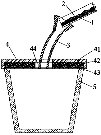
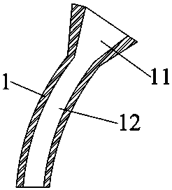
[0026] Such as figure 1 and figure 2 , this embodiment relates to a bushing for tapping, including a bushing body 3, the bushing body 3 defines an inner cavity, and the inner cavity forms a tapping channel, that is, during the tapping process, the molten iron 2 flows from the The sleeve body 3 flows into the molten iron storage and transportation equipment 5, which can isolate the molten iron 2 from the air, so that the tapping process can be carried out under the condition of sealing, heat preservation and protection as much as possible. The casing body 3 includes an upper funnel-shaped inlet section 11 and a lower column-shaped drainage section 12, the inlet section 11 is coaxially connected with the drainage section 12; the diameter of the top of the inlet section 11 is larger than the width of the molten iron chute 1 . The funnel-shaped inlet section 11 is provided to receive the molten iron 2 , and the top of the drainage section 12 communicates with the bottom of the ...

Embodiment 2

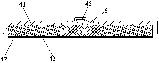
[0030] Such as Figure 3-Figure 4 , this embodiment relates to a thermal insulation cover 4, which is covered on the storage and transportation equipment for storing and transporting molten iron 2 or molten steel, and includes a casing 41 and a first thermal insulation body arranged on the inner surface of the casing 41. The casing 41 is provided with a liquid inlet, and the liquid inlet extends downwards and passes through the first heat insulating body to form a liquid inlet channel 44 . Wherein, the length, width or diameter of the liquid inlet should be greater than the diameter of the molten iron flow column or the molten steel flow column, so that the molten iron 2 or molten steel can enter the storage and transportation equipment along the liquid inlet channel 44 . By arranging the insulation cover 4, a near-closed inner chamber containing molten iron 2 / molten steel is formed with the body of the storage and transportation equipment, and the storage and transportation e...

Embodiment 3

[0036] Such as figure 1 , the present embodiment relates to a device for improving the energy efficiency of molten iron storage and transportation, including a thermal insulation channel and a thermal insulation cover 4 covered on the molten iron storage and transportation equipment 5, and the thermal insulation cover 4 and the molten iron storage and transportation equipment 5 body form a closed interior cavity, the heat preservation cover 4 is provided with an iron inlet 44, and the heat preservation channel extends from the outlet end of the molten iron chute 1 to the iron inlet 44. The above-mentioned heat preservation channel is preferably the tapping bushing described in Embodiment 1, and the above heat preservation cover 4 is preferably the heat preservation cover 4 described in Embodiment 2.


PUM

PropertyMeasurementUnit
thicknessaaaaaaaaaa

Abstract

The invention relates to a method for improving the storing and transporting energy efficiency of molten iron. A molten iron tank is provided with an insulating cover. A closed inner cavity can be defined by the insulating cover and the molten iron tank. The insulating cover is provided with a molten iron inlet. An insulating channel is formed to guide molten iron in a molten iron chute into the molten iron tank from the molten iron inlet. The invention further relates to a device for improving the storing and transporting energy efficiency of molten iron. The device comprises the insulating channel and the insulating cover covering the molten iron tank. The closed inner cavity is defined by the insulating cover and the molten iron tank. The insulating cover is provided with the molten iron inlet, and the insulating channel extends to the molten iron inlet from the outlet end of the molten iron chute. The molten iron discharging process proceeds under the sealing and insulating protection conditions to the greatest extent through the insulating channel and the insulating cover, and molten iron is prevented from being in direct contact with the surrounding environment in the molten iron discharging process and in the molten iron storing and transporting process. The loss of the effective heat in the molten iron to the surrounding environment is reduced, and the energy efficiency of the whole molten iron storing and transporting process is improved.

Description

technical field [0001] The invention belongs to the technical field of metallurgy, and in particular relates to a method and a device for improving the energy efficiency of molten iron storage and transportation. Background technique [0002] In the iron and steel smelting process, the high-temperature molten iron smelted in the blast furnace needs to be transported to the converter for further smelting through the molten iron tank, so as to obtain molten steel with qualified composition and temperature. The analysis of the entire molten iron storage and transportation process from the blast furnace to the converter shows that the energy consumption in the molten iron storage and transportation process includes the temperature loss of the molten iron and the power consumption of the transport locomotive. Among them, the temperature loss in the process of tapping and molten iron transportation is the most important energy consumption. In general, the temperature loss of molte...

Claims


Application Information

Patent Timeline
Patent Type & Authority Patents(China)
IPC IPC(8): B22D41/00
Inventor 徐海伦邵远敬叶理德
Owner WISDRI ENG & RES INC LTD
Why Eureka
Try Eureka