
Vertical push structure for thinning machine

A technology of thinning machine and vertical cylinder, which is applied in metal processing and other directions, can solve the problems of unstable transmission between piston rod and cylinder, and achieve the effect of simple structure, improved stability, and impact prevention.

Inactive Publication Date: 2015-12-16
SUZHOU SUPERLIGHT MICROELECTRONICS
View PDF6 Cites 0 Cited by
  • Summary
  • Abstract
  • Description
  • Claims
  • Application Information

AI Technical Summary

Problems solved by technology

[0003] The main technical problem to be solved by the present invention is to provide a vertical push structure used on a thinning machine, which has a reasonable design and a simple structure, and solves the problem of unstable transmission between the piston rod and the cylinder

Method used


Image

  • Vertical push structure for thinning machine

Examples


Embodiment Construction

[0009] The preferred embodiments of the present invention will be described in detail below with reference to the accompanying drawings, so that the advantages and features of the present invention can be more easily understood by those skilled in the art, so as to make a clearer and clearer definition of the protection scope of the present invention.

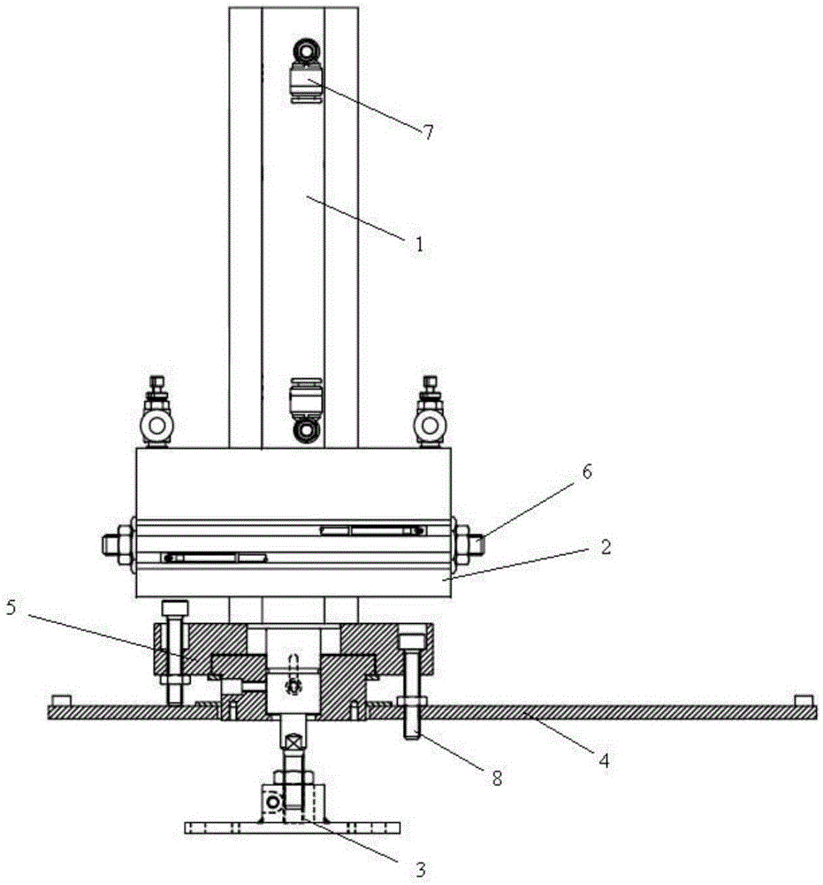
[0010] See attached figure 1 , The embodiment of the present invention includes:

[0011] A vertical pushing structure used on a thinning machine, comprising a vertical cylinder 1, a cylinder fixed plate 2, a T-shaped piston rod 3, and an end cover group; the T-shaped piston rod 3 is sleeved in the vertical cylinder 1 The outside of the vertical cylinder 1 is provided with a gas pipe pairing interface 7; the cylinder fixed plate 2 is fixed on the outside of the vertical cylinder 1 and is fastened by a double-ended screw 6; the front end of the vertical cylinder 1 is provided There is the end cover group; the end cover group include...


PUM


Abstract

The invention provides a vertical push structure for a thinning machine. The vertical push structure for the thinning machine comprises a vertical cylinder, a fixed cylinder disc, a T-shaped piston rod and an end cover set. The T-shaped piston rod is sleeved with the vertical cylinder. An air pipe joint is arranged at the outer portion of the vertical cylinder. The fixed cylinder disc is fixed to the outer portion of the vertical cylinder and fastened through a double-head screw. The end cover set is arranged at the front end of the vertical cylinder and comprises the front end cover and the rear end cover. The front end of the vertical cylinder is sleeved with the rear end cover in an interference fit manner. A shaft shoulder of the T-shaped piston rod is sleeved with the front end cover. A locating rod is further arranged between the front end cover and the rear end cover. In this way, the vertical push structure for the thinning machine is simple in structure, the axial fixing function can be achieved, stability of the piston rod in the feeding process is effectively improved, and impact in other directions is prevented.

Description

Technical field [0001] The invention relates to the field of microelectronic equipment, in particular to a vertical pushing structure used on a thinning machine. Background technique [0002] With the rapid development of science and technology, optical plastic lenses have been developed more and more widely, and they are widely used in mobile phones, digital cameras and video cameras with camera functions. At present, the cutting of optical plastic lenses mainly adopts two cutting methods. One is the manual cutting method. This method will make the labor intensity particularly high, and it is easy to contaminate the lens during the manual cutting process, so that the quality of the lens is improved. There is no guarantee, the rejection rate is high, and the production efficiency is low. The other is a fully automatic cutting method. Cutting an injection product requires two workbenches to cooperate with each other to complete the processing. The processing stations and steps ar...

Claims


Application Information

Patent Timeline
IPC IPC(8): B26D7/06
Inventor 乔金彪
Owner SUZHOU SUPERLIGHT MICROELECTRONICS
Learn More