
Steam pressure reduction power generation device

A power generation device and steam technology, applied in the direction of engine components, machines/engines, blade support components, etc., can solve the problems of low operating efficiency, low stand-alone power, high manufacturing cost per kilowatt, etc., to achieve small operation and maintenance workload, Improve the running stability and buffer the effect of steam pulsation

Inactive Publication Date: 2015-12-16
安徽新宁能源科技有限公司
View PDF7 Cites 8 Cited by
  • Summary
  • Abstract
  • Description
  • Claims
  • Application Information

AI Technical Summary

Problems solved by technology

[0002] The development of modern industry, economy and society has brought two problems that need to be solved urgently: one is the consumption of energy and the subsequent price rise; the other is the increasingly serious environmental pollution
The disadvantages of the screw expander are: the single unit power is small, the operation and maintenance costs are high, and the operating efficiency is low; the disadvantages of the axial flow steam turbine are: the manufacturing cost per kilowatt is high and the operating efficiency is usually not high when used for steam pressure difference power generation
[0005] To sum up, the vapor pressure difference recovery technology in the prior art has the disadvantages of low single-unit power, high operation and maintenance costs, and low operating efficiency

Method used


Image

  • Steam pressure reduction power generation device
  • Steam pressure reduction power generation device
  • Steam pressure reduction power generation device

Examples


Embodiment 1

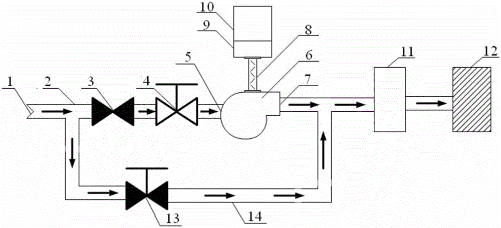
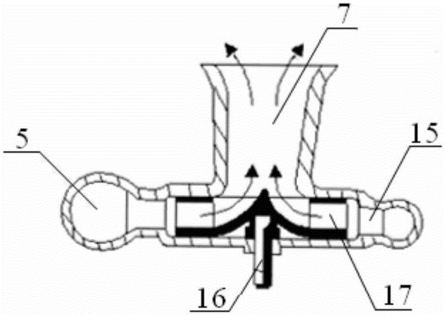
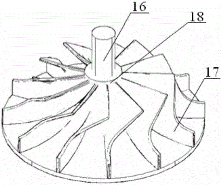
[0058] The rotating shaft 16 inside the radial steam turbine 6 drives the generator to generate electricity through the rotating shaft 7, and can also drive the fan and water pump power-consuming equipment. The speed of the steam turbine is converted into the speed required by the driven equipment.

Embodiment 2

[0060] A chemical plant needs to heat water vapor during the process, and the steam consumption is 70 tons per hour. The source steam pressure of the production process is 1.1 MPa, and the actual steam pressure is 0.42 MPa, which requires decompression of the steam. The radial steam turbine can be used to depressurize the steam, and at the same time output electric energy to avoid the waste of steam quality caused by direct throttling and depressurization.

[0061] After calculation, it can be seen that:

[0062] Steam enthalpy at the inlet of the steam turbine: 3166.8kJ / kg; enthalpy after steam turbine work: 3003.4kJ / kg; steam flow: 70000 / 3600=19.4kg / s;

[0063] Generating power: 2944kW; annual generating capacity: 20.61 million kWh.

Embodiment 3

[0065] Such as figure 1 In the steam decompression power generation device shown, in order to meet the different steam consumption requirements of the lower-level steam equipment, the steam pipeline 2 is also provided with a steam branch pipeline 14 to avoid the consumption of the steam source through the radial steam turbine. Regulating valve 13 adjusts and directly transports to the steam storage tank 11 for storage, meeting the requirements of lower-level steam consuming equipment for high-pressure steam.

[0066] The operation and maintenance workload of the system is small. The system is equipped with a normally closed bypass line. When the generator set is overhauled, the bypass steam pipe is opened, which does not affect the normal steam delivery of the factory. The generator set requires no energy and other operating costs other than steam. When downstream steam users intermittently use steam, causing steam pulsation in the pipe, as a preference, a steam storage tan...


PUM


Abstract

The invention discloses a steam pressure reduction power generation device which comprises a high-pressure steam inlet and a low-pressure steam device. A radial steam turbine is arranged on a steam pipeline between the high-pressure steam inlet and the low-pressure steam device and connected with a generator. According to the technical problem, superfluous energy in the steam pressure reduction process is recycled, and good energy saving benefits are generated. The generator can be driven to achieve power generation or a water pump, a fan and other energy consumption devices are dragged. The radial steam turbine has the beneficial effects of being low in maintenance workload, low in cost and high in running efficiency. A normal close bypass pipeline is adopted, and when a generator set breaks down and is maintained, a bypass steam pipeline is opened, and normal steam delivery of a factory is not influenced. The generator set needs no energy except steam or other running costs. When downstream steam users intermittently use steam, and pulsation of steam in pipes is caused, a steam storage tank is utilized for buffering pulsation of the steam, and the running stability of the radial steam turbine is improved.

Description

technical field [0001] The invention belongs to the technical field of energy saving and energy recycling. Specifically, the present invention relates to a steam decompression power generation device. Background technique [0002] The development of modern industry, economy and society has brought two problems that need to be solved urgently: one is the consumption of energy and the ensuing price rise; the other is the increasingly serious environmental pollution. All countries are committed to energy saving and reducing environmental pollution. my country's requirements for domestic enterprises' energy conservation and environmental protection are becoming more and more stringent. The National Energy Administration has issued guidelines that all enterprises with a heating capacity of 10-20t / h or more, a stable heat load, and an annual utilization time of more than 4,000 hours must conduct combined heat and power generation. Therefore, cogeneration of heat and power or co...

Claims


Application Information

Patent Timeline
Patent Type & Authority Applications(China)
IPC IPC(8): F01D15/10F01D9/04F01D5/34F01D17/10
Inventor 王章生周道宏
Owner 安徽新宁能源科技有限公司
Learn More