Compressor stator cascade with blade root provided with equal-width circular arc shaped channels

A technology of compressor and sub-leaf cascade, which is applied to the flow control scheme of compressor stator blade cascade blade root slotting, passive flow control, and compressor stator blade cascade flow control field, which can solve the problem of poor processing and difficult to optimize design of control scheme. , the direction of jet velocity cannot be controlled, etc., to achieve the effect of facilitating processing, good corner separation and inhibition effect, and easy to optimize design

Active Publication Date: 2015-12-16
BEIHANG UNIV
View PDF6 Cites 5 Cited by
  • Summary
  • Abstract
  • Description
  • Claims
  • Application Information

AI Technical Summary

Problems solved by technology

The above-mentioned technology has at least the following disadvantages: For engineering applications, the slotting scheme is relatively idealized, and the connecting arc is relatively random, which is not easy to process; especially the direction of the formed jet velocity cannot be controlled, and the angle with the mainstream direction may be large, resulting in " "step" flow to produce negative effects, making it difficult to optimize the design of the control scheme

Method used


Image

  • Compressor stator cascade with blade root provided with equal-width circular arc shaped channels
  • Compressor stator cascade with blade root provided with equal-width circular arc shaped channels
  • Compressor stator cascade with blade root provided with equal-width circular arc shaped channels

Examples


Embodiment Construction

[0023] The specific embodiments of the present invention will be described below with reference to the drawings.

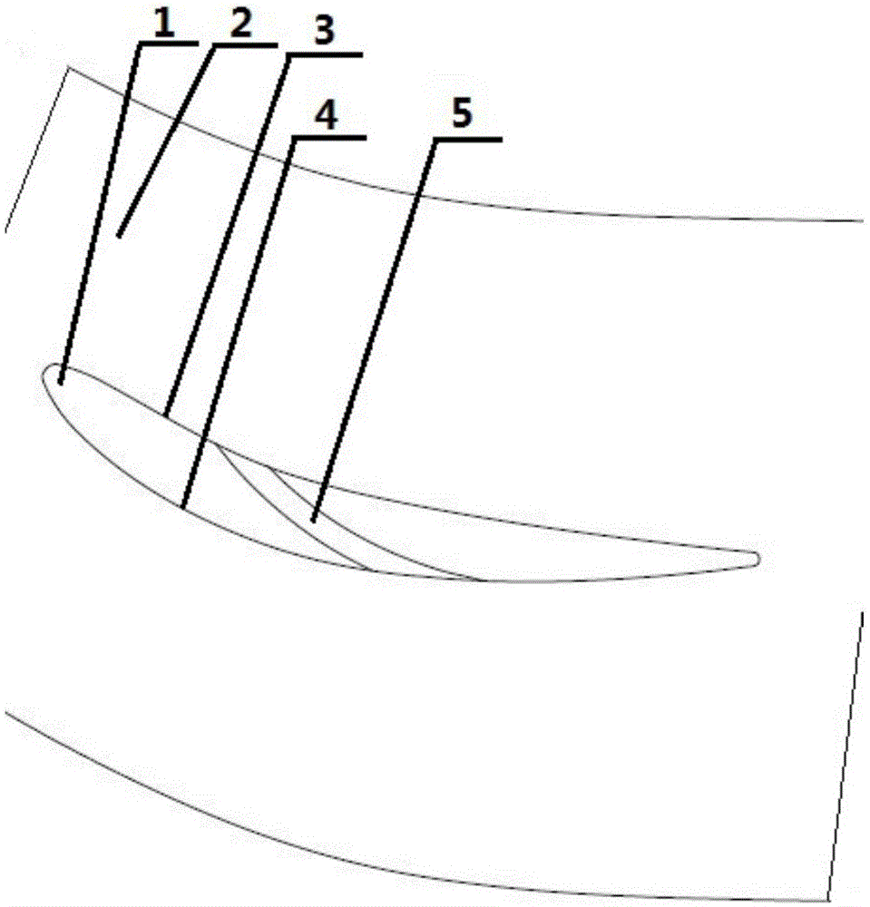
[0024] Such as figure 1 As shown, the blade root is provided with a compressor stator blade cascade of equal width circular arc grooves. At the root end wall 2 of the blade cascade 1, a circular arc channel 5 of equal width is opened from the pressure surface 3 to the suction surface 4 of the blade cascade 1.

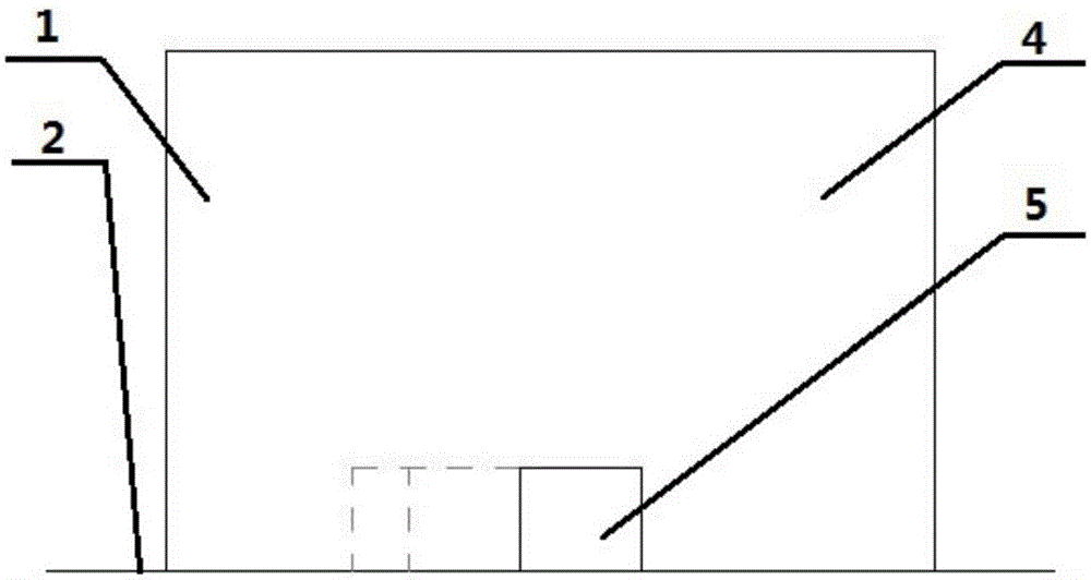
[0025] Such as figure 2 As shown, according to the flow field of the PVD prototype stator cascade, the outlet position of the channel 5 on the suction surface 4 is selected before the separation point; along the axis of the cascade, the inlet position of the channel 5 on the pressure surface 3 is located on the suction surface 4 Upstream of the outlet position; according to the surface pressure distribution of the PVD prototype stator cascade, the inlet position of the channel 5 on the pressure surface 3 is selected at the place where the static pressure on the ...


PUM


Abstract

The invention provides a compressor stator cascade with a blade root provided with equal-width circular arc shaped channels, relating to passive flow control technology in the technical field of turbo-machinery. The adverse pressure gradient resistance is stronger, Coanda effects are additionally brought and corner separation is better inhibited by forming the equal-width circular arc shaped channels in an end wall of the blade root of the compressor stator cascade from a pressure surface to a suction surface, forming high-speed jet by utilizing self-differential pressure of blades, increasing the kinetic energy of low energy fluid at a corner and blowing down airflows on boundary layers of the suction surface and the end wall. The compressor stator cascade is characterized in that the channels are formed in the end wall of the blade root of the compressor stator cascade; the spanwise height is a constant value; the number of the channels can be one or multiple; inlets of the channels are formed in the pressure surface of the stator cascade and outlets are formed in the suction surface of the cascade; center lines of the channels are shaped like circular arcs; the two sides of the channels are equally distant from the center lines; and the outlets in the side walls of the channels are tangent to the downstream wall of the suction surface of the cascade. The compressor stator cascade has the beneficial effects of effectively inhibiting corner separation, increasing the cascade flow capacity, reducing the total pressure loss and increasing the pressure diffusion capacity.

Description

Technical field [0001] The invention relates to the flow control of a compressor stator cascade, in particular to a flow control scheme for suppressing the separation of the compressor stator cascade blade roots, which belongs to the passive flow control technology in the technical field of impeller machinery. Background technique [0002] In the internal flow of the impeller machinery, the most complicated is the flow in the corner area. The corner area flow between the suction surface and the end wall has the end wall surface layer, the blade surface layer, various vortex structures and their interactions. The main factor causing deterioration of compressor stator performance. The flow separation in the corner area will cause channel blockage, blade load and diffusing capacity, resulting in total pressure loss and efficiency drop, and in severe cases, it will cause engine surge. The flow loss in the compressor stator corner area accounts for a large proportion of the total los...

Claims


Application Information

Patent Timeline
Patent Type & Authority Applications(China)
IPC IPC(8): F04D29/54
CPCF04D29/682F04D29/684
Inventor 柳阳威唐雨萌陆利蓬孙槿静
Owner BEIHANG UNIV
Why Eureka
Try Eureka