Two-stage multi-sheet electromagnetic clutch

An electromagnetic clutch, multi-plate technology, used in magnetic drive clutches, clutches, non-mechanical drive clutches, etc.

Active Publication Date: 2015-12-16
LONGKOU ZHONGYU MACHINERY
View PDF5 Cites 17 Cited by
  • Summary
  • Abstract
  • Description
  • Claims
  • Application Information

AI Technical Summary

Problems solved by technology

[0003] The purpose of the present invention is to improve the design of the magnetic circuit, the integrated design of the input shaft and the transmission housing in view of the technical defects in the prior art, so as to overcome the defects, make the clutch structure simple and use fewer parts , to solve a series of problems in clutch procurement, management, processing, manufacturing, etc.

Method used


Image

  • Two-stage multi-sheet electromagnetic clutch
  • Two-stage multi-sheet electromagnetic clutch
  • Two-stage multi-sheet electromagnetic clutch

Examples


Embodiment 1

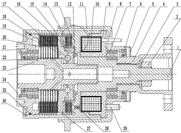
[0036] Embodiment 1: see figure 1 .

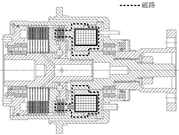
[0037] A two-stage multi-plate electromagnetic clutch. This device includes an input flange 4, which is splined with the input shaft 1 and fixed by a fastener 2. The input shaft 1 includes a traditional input shaft and The combined form of the traditional shell, and has the design of the magnetic passage. There is a magnetic isolation groove on the end surface of the input shaft close to the coil 10. The magnetic isolation groove is filled with non-magnetic materials, such as aluminum alloy, copper, etc., and the input shaft 1 passes through the input shaft. Bearing 7 is supported on housing 11, housing 11 is equipped with electromagnet assembly, electromagnet assembly includes coil 10 and iron core 9, electromagnet assembly is fixed on housing 11 by iron core bolt, the whole magnetic circuit includes iron core 9 , the input shaft 1 and the primary active friction plate 13, the primary driven friction plate 14 and the armature 15, the pri...


PUM


Abstract

The invention relates to a power cutting off and combination device, in particular to a two-stage multi-sheet electromagnetic clutch. The two-stage multi-sheet electromagnetic clutch comprises an input shaft with a left sleeve and a right sleeve, an output shaft pivoted to the input shaft, an electromagnet assembly pivoted to the input shaft, a primary clutch portion, a cam force increasing mechanism and a main clutch portion. Compared with the prior art, the two-stage multi-sheet electromagnetic clutch is simple in structure, fewer parts are used, and a series of problems of purchasing, management, machining, manufacturing and the like of the clutch are solved.

Description

technical field [0001] The invention relates to a power cut-off and combination device, in particular to a two-stage multi-plate electromagnetic clutch. Background technique [0002] The invention patent with the publication number CN10040676C "Electromagnetic Clutch Assembly with Solenoid Operator" discloses an electromagnetic force coupling assembly, which uses electromagnetic suction to compress the primary or pilot clutch, and drives the ball slideway accelerator to press through the primary clutch. Slave clutch device with tight master clutch. But this device still has certain defects: the gap between the coil and the pull-in disk is large, the magnetic force loss is serious when the clutch is working, and the suction force of the electromagnetic coil on the pull-in disk is small; and the input shaft and the transmission housing are It is made of two different materials and then connected by interference, which is cumbersome to manufacture and assemble. The material of...

Claims


Application Information

Patent Timeline
Patent Type & Authority Applications(China)
IPC IPC(8): F16D27/04B60K17/02
Inventor 王兆宇邢子义徐军领王庆海
Owner LONGKOU ZHONGYU MACHINERY
Why Eureka
Try Eureka