
Solar phase-change heat storage system

A phase change heat storage and solar energy technology, applied in the field of solar energy, can solve the problems of insufficient utilization of solar energy, reduced heat transfer coefficient, poor heat storage capacity, etc. Effect

Active Publication Date: 2015-12-16
SICHUAN YAOUDING NEW ENERGY TECH
View PDF6 Cites 4 Cited by
  • Summary
  • Abstract
  • Description
  • Claims
  • Application Information

AI Technical Summary

Problems solved by technology

However, the water circulation system of the solar thermal collection system is a closed system. The circulating water is circulated and heated, but some non-condensable gases will be produced during the circulating water circulation. In addition, sometimes the water in the collector will form when the sun is strong. Soda water and hot water, so in the case of heated water for heat exchange, the heat transfer coefficient is reduced due to the presence of non-condensable gas or the formation of soda water and hot water, so that solar energy cannot be fully utilized
[0005] In the existing solar heat storage system, basically non-phase change materials are used, such as water is used as the heat storage material, and the heat storage capacity is poor.
[0006] In view of the above problems, the present invention provides a new solar heat storage system, thereby solving the problem of low heat transfer coefficient and poor heat storage capacity in the case of heat exchange between solar hot water and its fluid

Method used


Image

  • Solar phase-change heat storage system
  • Solar phase-change heat storage system
  • Solar phase-change heat storage system

Examples


Embodiment Construction

[0049] The specific embodiments of the present invention will be described in detail below in conjunction with the accompanying drawings.

[0050] In this article, if there is no special explanation, when it comes to formulas, " / " means division, and "×" and "*" mean multiplication.

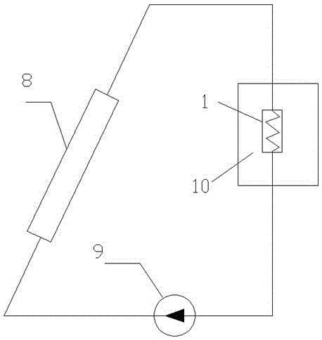
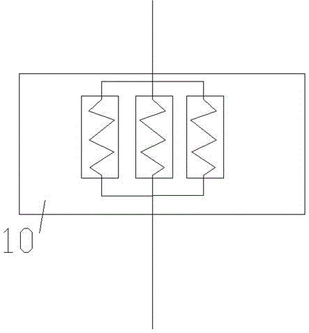
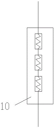
[0051] Such as figure 1 As shown, a solar heat storage system includes a heat collector 8, a heat storage box 10, and a heat dissipation pipe 1. The heat dissipation pipe 1 is arranged in the heat storage box 10, and the hot water heated by the heat collector 8 is radiated The pipe 1 transfers heat to the heat storage material in the heat storage box 10 through the heat dissipation pipe 1, and the hot water after heat exchange circulates back to the heat collector 8 for heating. It is preferably circulated into the heat collector 8 via a circulation pump 9 .

[0052] A phase-change heat-storage material is arranged in the heat-storage box, and the material of the phase-change heat-storage materia...


PUM


Abstract

The invention provides a solar phase-change heat storage system. The solar phase-change heat storage system comprises a heat collector, a heat storage box and radiating tubes. The radiating tubes are arranged in the heat storage box, water heated by the heat collector passes through the radiating tubes, and heat is transferred to the heat storage box through the radiating tubes. The solar phase-change heat storage system is characterized in that a phase-change heat storage material is arranged in the heat storage box. The phase-change material is arranged to serve as a heat storage material, so that heat storage capacity is high, and energy is greatly saved.

Description

technical field [0001] The invention belongs to the field of solar energy, in particular to a heat storage solar energy system. Background technique [0002] With the rapid development of modern society and economy, the human demand for energy is increasing. However, the reserves of traditional energy such as coal, oil, and natural gas continue to decrease and become increasingly scarce, resulting in rising prices. At the same time, the environmental pollution caused by conventional fossil fuels is also becoming more and more serious. These greatly limit the development of society and the improvement of human life quality. . Energy issues have become one of the most prominent issues in the contemporary world. Therefore, seeking new energy sources, especially non-polluting clean energy sources has become a research hotspot. [0003] Solar energy is an inexhaustible clean energy with a huge amount of resources. The total amount of solar radiation energy received by the eart...

Claims


Application Information

Patent Timeline
IPC IPC(8): F24J2/34F24J2/30F24J2/46F24S10/30
CPCY02E10/44
Inventor 刘习武王艳艳李晴朱士强鲁阳程文平杨东赵炜
Owner SICHUAN YAOUDING NEW ENERGY TECH
Learn More