

Mixed biasing type articulated arm measurement machine
An articulated arm and measuring machine technology, applied in the field of measuring machines, can solve the problems of increasing the moment of inertia of each articulated arm, reducing the rotation angle of the articulated arm, reducing the flexibility of operation, etc. light weight effect
- Summary
- Abstract
- Description
- Claims
- Application Information
AI Technical Summary
Problems solved by technology
Method used
Image

Examples
Embodiment 1
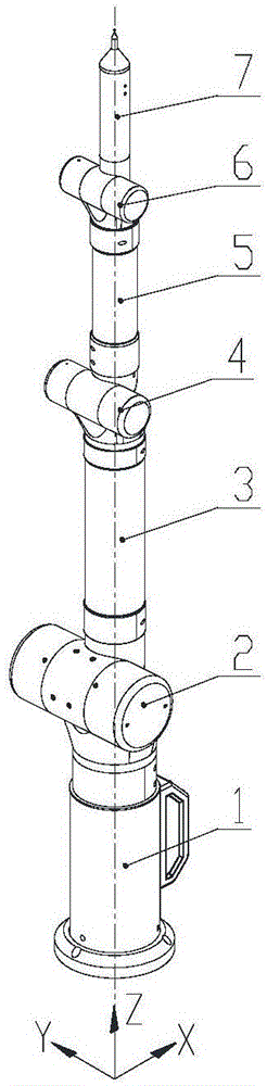
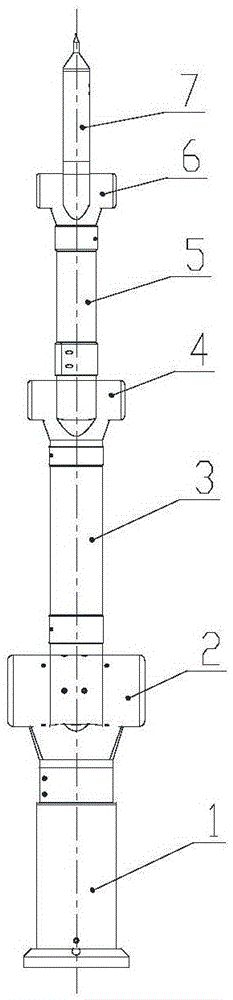
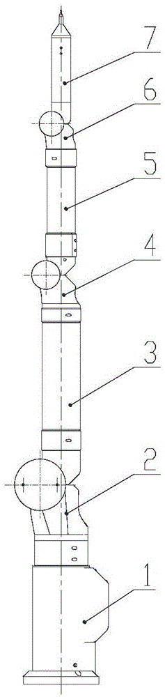
[0071] The hybrid offset articulated arm measuring machine consists of a first long-axis part 1, a first short-axis part 2, a second long-axis part 3, a second short-axis part 4, a third long-axis part 5, and a third short-axis part 6 , Measuring head connecting arm 7 are jointly composed.
[0072] The first long-axis component, the screw 18 fixes the first long-axis dense ball shaft system 19 on the first long-axis housing 12, the code disc seat 17, the code disc 30, the code disc pressure ring washer 33 and the code disc pressure ring 29 They are sequentially installed on the long axis I31 through hole-shaft fit, and the screws 16 are rigidly connected to the first long-axis dense ball shafting 19 . The reading head bracket 13 is screwed to the first long axis housing 12 , and the screw 15 rigidly connects the reading head 14 to the reading head bracket 13 . The cover plate 11 is rigidly fixed on the first long-axis housing 12 by screws 10, and the seal ring 20 is installed...
Embodiment 2
[0085] The offset in the first short axis part 2, the second short axis part 4 and the third short axis part 6 is removed, and the first long axis part 1, the second long axis part 3, the reading head slip ring assembly 113, The third long-axis part 5 and the probe connecting arm 7 undergo corresponding shape changes, becoming the first long-axis part 174, the first short-axis part 173, the second long-axis part 172, the second short-axis part 171, and the reading head The slip ring assembly 170 , the third major axis component 169 , the third short axis component 168 and the probe connection arm 167 . Both the second long arm 88 and the third long arm 114 are transformed from a cylindrical thin-walled pipe into two completely symmetrical oval cylindrical thin-walled pipes arranged symmetrically along the YZ plane and symmetrically designed along the ZX plane. That is, a non-biased articulated arm measuring machine (such as Figure 35 shown).
[0086] The non-offset articula...
PUM
 Abstract
Description
Claims
Application Information