Screen dot structure and preparation method thereof, backlight module and liquid crystal display device
A liquid crystal display device and backlight module technology, applied in the direction of light guides, optics, optical components, etc., can solve the problems of increasing the overall cost, module thickness, and low hardness of the light guide plate, so as to improve light extraction efficiency, improve extraction efficiency, reduce Effect of small loss of light
- Summary
- Abstract
- Description
- Claims
- Application Information
AI Technical Summary
Problems solved by technology
Method used
Image

Examples
Embodiment 1
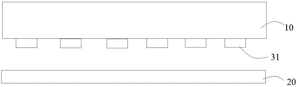
[0034] ginseng figure 2 As shown, a dot structure in Embodiment 1 of the present invention, the dot structure is located between the light guide plate 10 and the reflection sheet 20, the dot structure includes a number of scattering dots 31 formed protrudingly on the light guide plate 10, and adhering scattering dots The optical glue layer (not shown) with the reflection sheet, and the thickness of the dot structure is 2um-100um.
[0035] In the present embodiment, the scattering dots 31 are spacer ink scattering dots formed by mixing spacers and ink, and the material of the spacers is glass fiber, PS, SiO 2 、TiO 2 , ZnO, etc. in one or more. Through the screening of spacer size, the spacer and ink are mixed to form a new type of ink dot material.
[0036] The dot structure has the function of the existing dots, and can also support the gap between the light guide plate and the reflector. Since the dot structure (that is, the gap) is greater than 2um, when the light reache...
Embodiment 2
[0046] ginseng Figure 5 As shown, Embodiment 2 of the present invention discloses a backlight module, including a light source 40, a light guide plate 10, and a reflective sheet 20. The side, the side adjacent to the light source is the light incident surface of the light guide plate, the reflection sheet includes a first surface and a second surface opposite to each other, the first surface is located adjacent to the light guide plate.
[0047] Wherein, a dot structure is formed between the bottom surface of the light guide plate and the first surface of the reflector, and the dot structure includes a plurality of scattering dots 31 protruding from the light guide plate, and an optical glue layer that sticks the scattering dots and the reflector (not shown), the thickness of the dot structure is 2um˜100um. The dot structure in this embodiment is completely the same as that in Embodiment 1, and will not be repeated here.
Embodiment 3
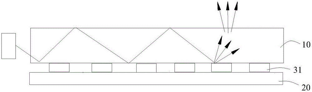
[0049] ginseng Image 6 As shown, a backlight module in Embodiment 3 of the present invention is basically similar to Embodiment 2. A dot structure is formed between the bottom surface of the light guide plate and the first surface of the reflector. The dot structure includes protrusions formed on the A number of scattering dots 31 on the light plate, and an optical adhesive layer (not shown) that adheres the scattering dots and the reflective sheet, but different from Embodiment 2, a number of second dots are arranged on the light-emitting surface of the light guide plate The structure 32, the second dot structure can be spherical or other shapes of scattering dots.
[0050] Because the dot structure has the effect of destroying total reflection, part of the light can be taken out at the dot structure. In order to make the light distribution uniform, a second dot is set on the light-emitting surface to supplement the light taken out by the dot structure on the bottom of the l...
PUM
| Property | Measurement | Unit |
|---|---|---|
| Thickness | aaaaa | aaaaa |
| Thickness | aaaaa | aaaaa |
Abstract
Description
Claims
Application Information
 - Generate Ideas
- Intellectual Property
- Life Sciences
- Materials
- Tech Scout
- Unparalleled Data Quality
- Higher Quality Content
- 60% Fewer Hallucinations
Browse by: Latest US Patents, China's latest patents, Technical Efficacy Thesaurus, Application Domain, Technology Topic, Popular Technical Reports.
© 2025 PatSnap. All rights reserved.Legal|Privacy policy|Modern Slavery Act Transparency Statement|Sitemap|About US| Contact US: help@patsnap.com