Intelligent home controller based on eye-movement tracking and intelligent home control method based on eye-movement tracking

A smart home and eye-tracking technology, applied in computer control, comprehensive factory control, electrical program control, etc., can solve the problem that key or touch input methods cannot be applied to special groups with physical disabilities, so as to increase the fun of life and reduce the Effects of interference and burden reduction

Inactive Publication Date: 2015-12-16
HARBIN UNIV OF SCI & TECH
View PDF3 Cites 28 Cited by
  • Summary
  • Abstract
  • Description
  • Claims
  • Application Information

AI Technical Summary

Problems solved by technology

[0004] The purpose of the present invention is to solve the problem that the button or touch input method adopted by the existing smart home control system cannot be applied to special people with physical disabilities, and propose a smart home controller based on eye movement tracking and its control method

Method used


Image

  • Intelligent home controller based on eye-movement tracking and intelligent home control method based on eye-movement tracking
  • Intelligent home controller based on eye-movement tracking and intelligent home control method based on eye-movement tracking
  • Intelligent home controller based on eye-movement tracking and intelligent home control method based on eye-movement tracking

Examples


specific Embodiment approach 1

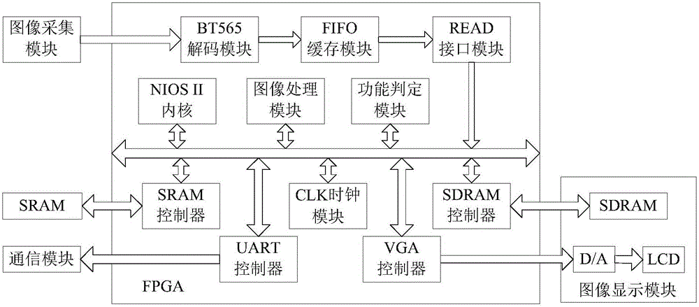
[0059] The smart home controller based on eye tracking in this embodiment, combined with figure 2 The eye-tracking smart home control system shown includes:

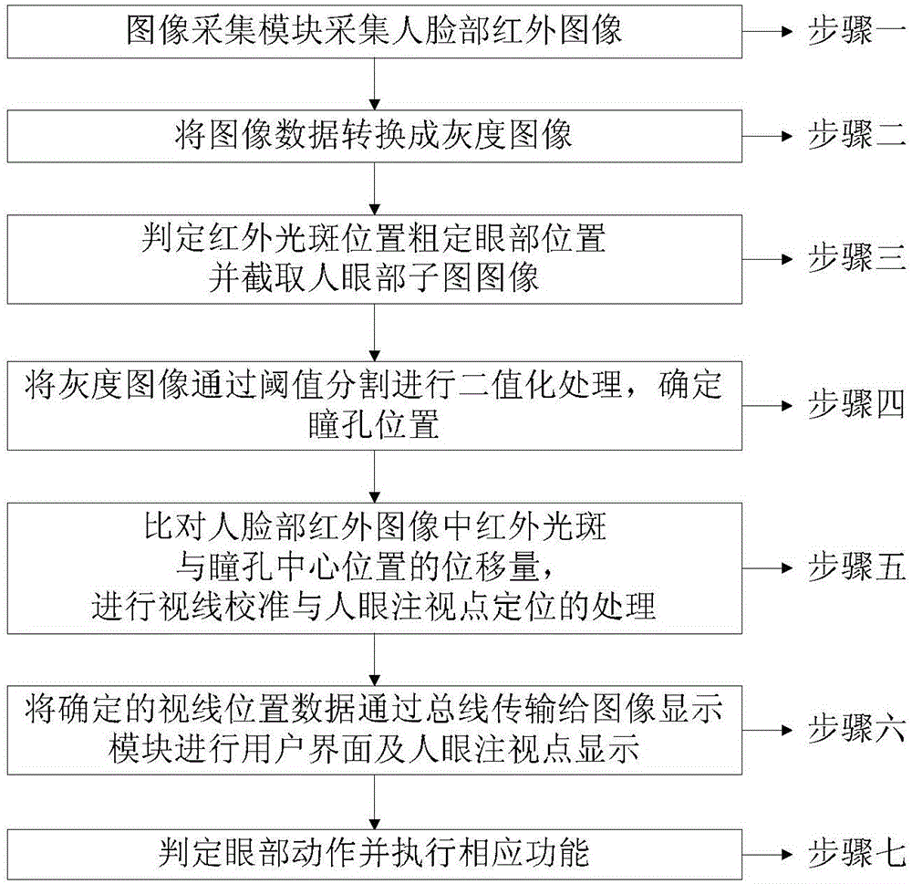
[0060] An image acquisition module for acquiring infrared images of human faces;

[0061] An image display module for displaying the designed user interface and the position of the user's line of sight on the liquid crystal display to realize human-computer interaction;

[0062] A communication module used to issue instructions from the processor to control indoor electrical appliances;

[0063] and FPGA modules;

[0064] And the FPGA module includes FPGA chips and SRAM chips:

[0065] Among them, the FPGA chip is internally integrated:

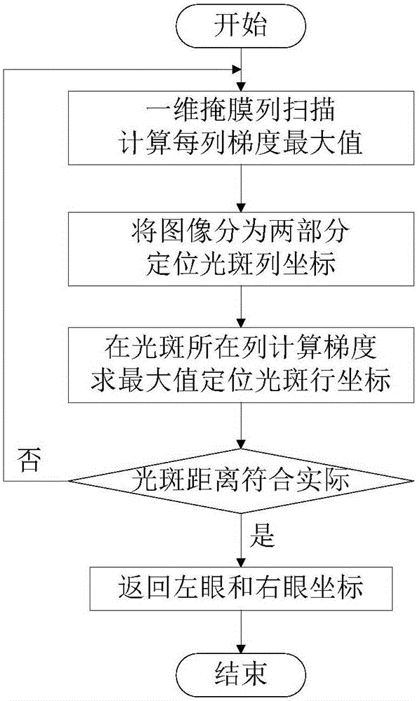
[0066] An image processing module for binarizing the infrared image of the human face collected by the image acquisition module, finding out the spot position of the human pupil and the infrared light on the sclera of the human eye, and estimating the line of sight direction of the...

specific Embodiment approach 2

[0077] Different from Embodiment 1, in the smart home controller based on eye movement tracking in this embodiment, the image acquisition module further includes:

[0078] an infrared LED lighting module for emitting near-infrared light, and

[0079] A CMOS camera module used to capture infrared images of human faces formed after the infrared LED light-emitting module emits light.

specific Embodiment approach 3

[0080] Different from the specific embodiment 1 or 2, in the smart home controller based on eye movement tracking in this embodiment, the image display module further includes:

[0081] FPGA chips for control signals,

[0082] A digital-to-analog conversion (D / A) module for converting user interface image data into an analog signal,

[0083] SDRAM memory module for storing user interface image data, and

[0084] VGA LCD for displaying analog signals.


PUM


Abstract

The invention relates to an intelligent home controller based on eye-movement tracking and an intelligent home control method based on eye-movement tracking, and belongs to the field of wireless control. The problem that the existing intelligent home controller adopts a press key or touch input mode, so that the existing intelligent home controller cannot be applicable to special user groups with limb obstacles. The intelligent home controller based on eye-movement tracking comprises an image collecting module, an image processing module, a communication module, an FPGA (Field Programmable Gate Array) module and a sub module, wherein the sub module is integrated inside an FPGA chip. The intelligent home control method based on the eye-movement tracking comprises the steps that: the image processing module performs binarization processing on collected face images; the human eye pupils and the light spot positions, displayed on the human eye scleras, of an infrared lamp are found out; the sight line direction of the human eye is estimated; and in a VGA (Video Graphics Array) liquid crystal display, the designed user interface and the user slight line position are displayed in the liquid crystal display screen by the image display module, and the human-computer interaction is realized. A non-contact control mode is adopted, so that the interference on users is reduced to the greatest degree, and the burden of the user is lightened.

Description

technical field [0001] The invention relates to an eye-tracking smart home controller and a control method thereof. Background technique [0002] Smart Home is the embodiment of connectionization under the impact of Internet of Things. The smart home system connects various existing household devices together through network technology, and provides various functions and means such as home appliance control, lighting control, telephone remote control, and environmental monitoring. Smart homes not only have traditional residential functions, but also include construction, network communications, information appliances, and equipment automation, providing a full range of information interaction functions, and even saving energy costs for occupants. [0003] The operation terminal with wireless communication function can enable the occupants to conveniently control the household appliances and obtain the required information. Existing wireless operation terminals include smar...

Claims


Application Information

Patent Timeline
Patent Type & Authority Applications(China)
IPC IPC(8): G06F3/01G05B19/418G05B15/02
Inventor 王鹏邵明磊李东滨梁超李琳琳
Owner HARBIN UNIV OF SCI & TECH
Why Eureka
Try Eureka