Micro-pulse laser radar light source with high pulse energy

A high pulse energy, laser radar technology, applied in the direction of lasers, laser components, phonon exciters, etc., can solve the problem of detection with greater distance and higher precision, the influence of output energy and beam quality, and the output of laser light source Problems such as small pulse energy can achieve the effect of improving detection distance and detection accuracy, improving pulse energy and beam quality, and compensating loss

Inactive Publication Date: 2015-12-16
HEFEI INSTITUTES OF PHYSICAL SCIENCE - CHINESE ACAD OF SCI
View PDF5 Cites 8 Cited by
  • Summary
  • Abstract
  • Description
  • Claims
  • Application Information

AI Technical Summary

Problems solved by technology

Thermally induced birefringence will cause thermal depolarization of the linearly polarized light passing through the laser rod, and the depolarized beam will be reflected out of the resonator when passing through the polarizer, which will seriously affect

Method used


Image

  • Micro-pulse laser radar light source with high pulse energy

Examples


Example Embodiment

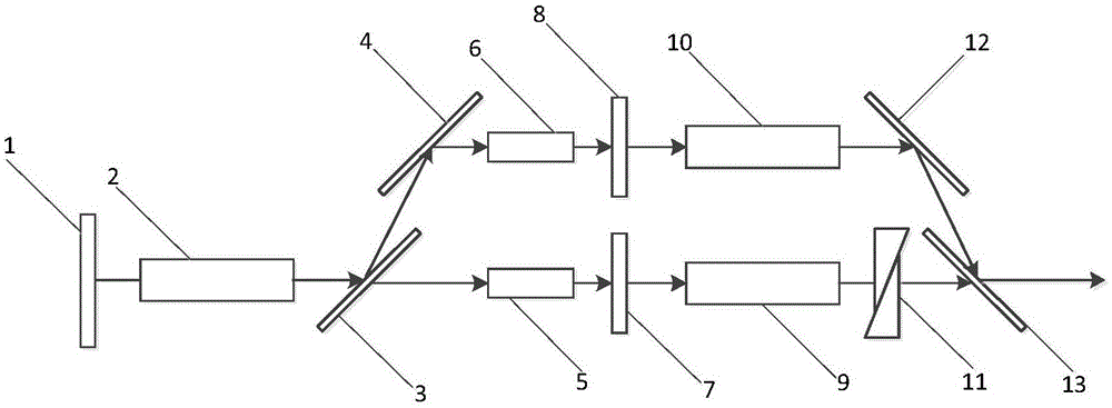
[0015] The working mode of the present invention will be further described in detail below in conjunction with the accompanying drawings.

[0016] like figure 1 As shown, the high pulse energy micro-pulse laser radar light source of the present invention includes: an oscillation stage and an amplification stage, the optical path of the amplification stage is coaxial with the optical path of the oscillation stage; Loss, the two-way output is amplified by a separate amplifier stage and then combined, and finally achieves the function of compensating for thermal depolarization and performing energy amplification.

[0017] The resonant cavity is composed of total reflection mirror 1, laser crystal rod (Nd:YAG) 2, dielectric film polarizers 3 and 4, Pockels cells 5 and 6, coupling output mirrors 7 and 8. Among the above optical components, the dielectric film polarizers 3 and 4 are placed at the Brewster angle, and the incident surfaces of other components are placed parallel to e...


PUM


Abstract

The invention relates to a micro-pulse laser radar light source with high pulse energy. The light source is formed by an oscillator stage and an amplifier stage; and the light path of the amplifier stage and the light path of the oscillator stage are in a coaxial mode. At the oscillator stage, a dual-path Q switch is used for compensating thermal depolarization loss of a laser; dual-path outputs are amplified respectively by the independent amplifier stage and then are combined, thereby realizing functions of thermal depolarization compensation and energy amplification. At the oscillator stage, a holophote, a laser crystal rod, two dielectric film polarizers, two Pockels boxes, and two output coupling mirrors are successively arranged on the light path; the two dielectric film polarizers are arranged at a brewster angle, incident surfaces of other elements are parallel to each other; and two end surfaces of the laser crystal rod are parallel to each other. According to the invention, losses of output energy by thermal depolarization can be compensated and the output energy can be amplified further; compared with the prior art, the conversion efficiency, the pulse energy, and the light beam quality of the light source are substantially improved; and the detection distance and detection precision of the micro-pulse laser radar are enhanced.

Description

technical field [0001] The invention relates to a high pulse energy micro-pulse laser radar light source, belonging to the technical field of micro-pulse laser radar. Background technique [0002] Micropulse lidar has important applications in the fields of atmospheric detection and other fields due to its advantages of small size and high echo signal frequency per unit time. When the laser as a radar light source works at high repetition rate and high pump power, the thermal deposition in the laser rod will lead to non-uniform distribution of the refractive index in the rod section, resulting in thermally induced birefringence. Thermally induced birefringence will cause thermal depolarization of the linearly polarized light passing through the laser rod, and the depolarized beam will be reflected out of the resonator when passing through the polarizer, which will seriously affect the output energy and beam quality . Due to the limitation of the thermal depolarization effe...

Claims


Application Information

Patent Timeline
IPC IPC(8): H01S3/08H01S3/094
Inventor 王礼杨经纬王金涛邢廷伦崔庆哲胡舒武程庭清吴先友江海河
Owner HEFEI INSTITUTES OF PHYSICAL SCIENCE - CHINESE ACAD OF SCI
Why Eureka
Try Eureka