Optical fiber output large-power semiconductor laser module

A technology of lasers and semiconductors, applied in semiconductor lasers, the structural details of semiconductor lasers, lasers, etc., can solve problems such as low coupling efficiency, and achieve the effect of improving coupling efficiency and reducing the impact of reliability.

Inactive Publication Date: 2015-12-16
THE 44TH INST OF CHINA ELECTRONICS TECH GROUP CORP
5 Cites 1 Cited by

AI-Extracted Technical Summary

Problems solved by technology

However, the inventors of the present invention have found through research that since the diameter of the output optical fiber is fixed, if the o...

Abstract

The invention discloses an optical fiber output large-power semiconductor laser module. The optical fiber output large-power semiconductor laser module comprises a semiconductor laser module to be coupled, metalized optical fibers and an optical fiber support. The semiconductor laser module to be coupled comprises a metal tube shell provided with a cavity body, and a welding support, an AlN heat sink and a laser chip which are successively fixed in the cavity body by welding. The metalized optical fibers comprise an output optical fiber and a self-focusing lens optical fiber. The self-focusing lens optical fiber comprises a self-focusing optical fiber and a lens arranged on one end surface of the self-focusing optical fiber, and the other end surface of the self-focusing optical fiber is welded with the output optical fiber. The aperture of the self-focusing lens optical fiber is larger than that of the output optical fiber, and the aperture of the self-focusing lens optical fiber is matched with the width of a luminous zone of the laser chip. The optical fiber support is fixed to the welding support by welding. The self-focusing lens optical fiber is fixed to the optical fiber support by welding. The self-focusing lens optical fiber and the laser chip are coupled and aligned. According to the invention, the aperture of the self-focusing optical fiber is matched with the width of the luminous zone of the laser chip, and all components in the laser module are fixed in a non-glue welding manner.

Application Domain

Laser detailsSemiconductor laser structural details

Technology Topic

Heat sinkSemiconductor laser theory +5

Image

  • Optical fiber output large-power semiconductor laser module
  • Optical fiber output large-power semiconductor laser module
  • Optical fiber output large-power semiconductor laser module

Examples

  • Experimental program(1)

Example Embodiment

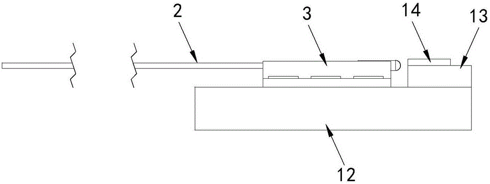
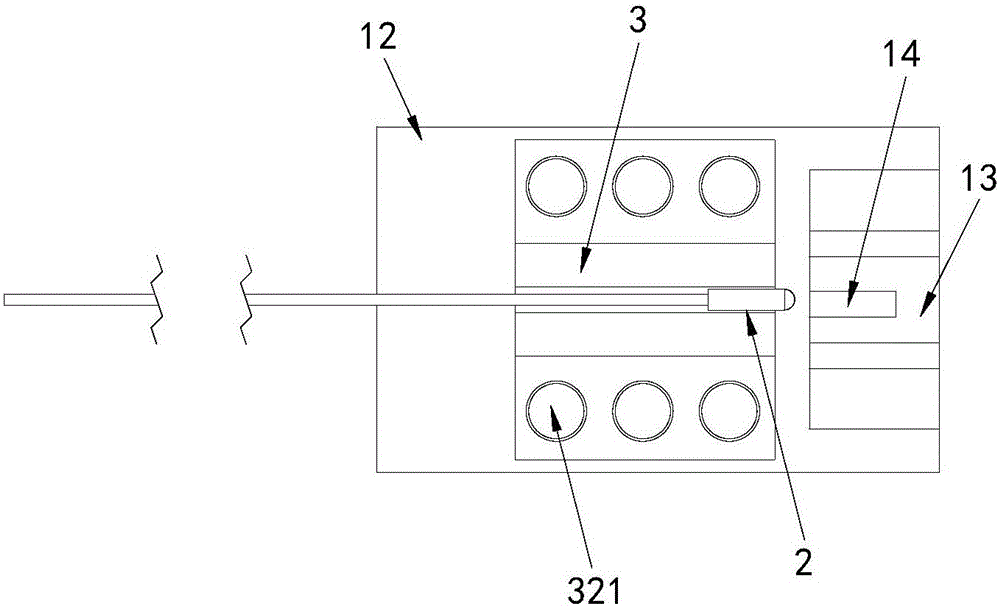
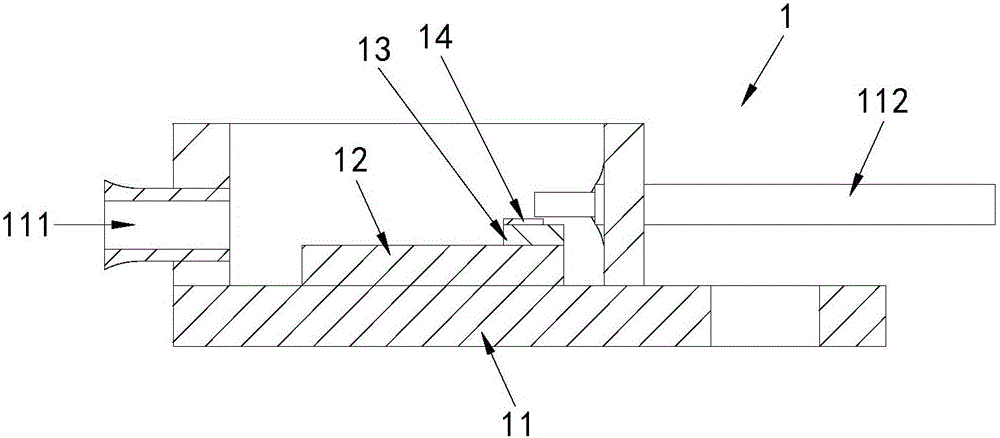
[0034] As a specific embodiment, the welding bracket 12 , the AlN heat sink 13 and the laser chip 14 are welded and fixed by metal solder. As an embodiment, Au80Sn20 (gold-tin alloy) solder is used for welding between the laser chip 14 and the AlN heat sink 13, and PbSn (lead-tin alloy) solder is used for welding between the AlN heat sink 13 and the welding bracket 12, The welding bracket 12 and the metal tube shell 11 are welded with In (indium) solder, thereby realizing that all the components inside the metal tube shell 11 are fixed by metal solder welding, that is, the glue-free welding and fixing are realized, thereby The influence of organic matter volatilization on the reliability of the laser chip is reduced. In particular, Au80Sn20 solder is used for welding between the laser chip 14 and the AlN heat sink 13 , and the Au80Sn20 solder has relatively stable characteristics under high and low temperature cycle conditions, so effective welding between the laser chip 14 and the AlN heat sink 13 can be achieved. .
[0035] As a specific example, please refer to Figure 4 As shown, the metallized optical fiber 2 includes an output optical fiber 21 and a self-focusing lens optical fiber 22. The self-focusing lens optical fiber 22 includes a self-focusing optical fiber 221 and a lens 222 polished on one end of the self-focusing optical fiber 221. The other end face of the self-focusing optical fiber 221 is fused to the output optical fiber 21 , the aperture of the self-focusing lens optical fiber 22 is larger than that of the output optical fiber 21 , and the aperture of the self-focusing lens optical fiber 22 matches the width of the light-emitting area of ​​the laser chip 14 . Specifically, the lens 222 on one end face of the self-focusing optical fiber 221 is formed by grinding and polishing, and the aperture of the lens 222 is equal to that of the self-focusing optical fiber 221, that is, the aperture of the self-focusing optical fiber 221 is the aperture of the self-focusing lens optical fiber 22, Then, the other end face of the self-focusing optical fiber 221 is spliced ​​with the output optical fiber 21 , and finally the fused optical fiber is metallized to form the metallized optical fiber 2 . In this embodiment, the aperture of the self-focusing lens optical fiber 22 is larger than that of the output optical fiber 21, and the aperture of the self-focusing lens optical fiber 22 is matched with the width of the light-emitting area of ​​the laser chip 14, so as to maintain the laser chip The coupling efficiency is improved under the condition that the width of the light-emitting region remains unchanged.
[0036] As a preferred embodiment, the fusion point between the other end face of the self-focusing optical fiber 221 and the output optical fiber 21 is located at the focal point of the self-focusing optical fiber 221 , so that light with maximum energy can be collected from the laser chip 14 .
[0037] As a preferred embodiment, the lens 222 polished on one end face of the self-focusing optical fiber 221 is hemispherical, so that the numerical aperture of the self-focusing optical fiber can be increased.
[0038] As a preferred embodiment, the radius of the hemispherical lens 222 is 300-400 microns, so that the coupling efficiency can be improved.
[0039] As a specific example, please refer to Figure 5 As shown, the optical fiber support 3 includes an optical fiber fixing part 31 and a laser welding part 32 located on both sides of the optical fiber fixing part 31. The matching U-shaped groove 311 can prevent the self-focusing fiber 221 from being displaced in the radial direction of the groove 311 when the self-focusing fiber 221 is welded and fixed to the groove 311, so as to achieve better performance. Welding to ground. The optical fiber support 3 is welded and fixed on the welding support 12 by the laser welding part 32, and a plurality of laser welding spots 321 are also arranged on the laser welding part 32, and the laser welding spots 321 are laser welded. Forming.
[0040] As a preferred embodiment, the fiber holder 3 is made of N6 (nickel material) and is provided with a U-shaped groove, thereby improving the reliability of the fiber fixing point at high and low temperatures.
[0041] As a preferred embodiment, the self-focusing optical fiber is welded and fixed in the U-shaped groove of the optical fiber fixing part using Au80Sn20 solder, so that the long-term stability of the welding point can be improved.
[0042] As a specific embodiment, both the optical fiber support and the welding support and between the self-focusing lens optical fiber and the fiber support are welded and fixed by a laser welding process. Specifically, after all the components inside the semiconductor laser module 1 to be coupled are welded and assembled, the semiconductor laser module 1 to be coupled and the metallized fiber 2 are coupled and aligned, that is, the self-focusing lens fiber 22 The front lens 222 is coupled and aligned with the laser chip 14 (belongs to active alignment), and is detected by a power meter connected to the output fiber 21. When it is detected that the coupling efficiency reaches the maximum, laser welding is used to The welding bracket 12 and the laser welding part 32 of the optical fiber bracket 3 are welded and fixed, and then metal solder is used to weld and fix the self-focusing optical fiber 221 of the metallized optical fiber 2 and the groove 311 of the optical fiber bracket 3, and finally complete The invention provides the manufacture of the optical fiber output high-power semiconductor laser module.

PUM

PropertyMeasurementUnit
Radius300.0 ~ 400.0µm

Description & Claims & Application Information

We can also present the details of the Description, Claims and Application information to help users get a comprehensive understanding of the technical details of the patent, such as background art, summary of invention, brief description of drawings, description of embodiments, and other original content. On the other hand, users can also determine the specific scope of protection of the technology through the list of claims; as well as understand the changes in the life cycle of the technology with the presentation of the patent timeline. Login to view more.

Similar technology patents

Polarization-independent lithium niobate optical isolator

ActiveCN112711147AIncrease applicability and ease of useImprove coupling efficiency
Owner:INST OF SEMICONDUCTORS - CHINESE ACAD OF SCI

Avalanche photodiode based on multi-period Bragg reflector and preparation method thereof

PendingCN113707731AImprove coupling efficiencyEnhanced light absorption
Owner:XIDIAN UNIV

Optical touch module based on lattice grating structures in two vector directions

PendingCN114020178AImprove output efficiencyImprove coupling efficiency
Owner:SHANGHAI JIAO TONG UNIV

Semiconductor laser for 50: 50 split optical fiber coupling output, and method

PendingCN113161860AImprove coupling efficiencyhigh beam quality
Owner:THE FIRST RES INST OF MIN OF PUBLIC SECURITY +1

Pupil compensation device and photoetching machine

ActiveCN112015053AImprove coupling efficiencySimple structure
Owner:SHANGHAI MICRO ELECTRONICS EQUIP (GRP) CO LTD

Classification and recommendation of technical efficacy words

  • Improve coupling efficiency

LNOI spot size converter based on sub-wavelength grating, and preparation method

ActiveCN112782805ALower effective refractive indexImprove coupling efficiency
Owner:NO 55 INST CHINA ELECTRONIC SCI & TECHNOLOGYGROUP CO LTD

Hollow magnetic core device for wireless charging and wireless power supply

InactiveCN104347257AImprove coupling efficiencyhigh efficiency coupling
Owner:天津榕丰科技有限公司

Method for coupling silicon-based optoelectronic chip and single-mode optical fiber

PendingCN109407215AImprove coupling efficiencyImprove coupling tolerance
Owner:HANGZHOU XIN YUN TECH CO LTD

Water-jet guided laser processing device and method

PendingCN109551103AImproved maneuverability and adjustabilityImprove coupling efficiency
Owner:GUILIN UNIV OF ELECTRONIC TECH

Aspheric fiber coupling lens

InactiveCN101566710AHigh positioning accuracyImprove coupling efficiency
Owner:E PIN OPTICAL IND
Why Eureka
Try Eureka