A current collector for a motor
A current collecting device and collector ring technology, which is applied in electromechanical devices, cooling/ventilation devices, electrical components, etc., can solve the problems of being unable to carry high voltage and high current, failing to meet the requirements of heat dissipation, and poor heat dissipation. Achieve the effects of improving heat dissipation effect, simple manufacturing process, and improving heat dissipation efficiency
- Summary
- Abstract
- Description
- Claims
- Application Information
AI Technical Summary
Problems solved by technology
Method used
Image

Examples
Embodiment 1
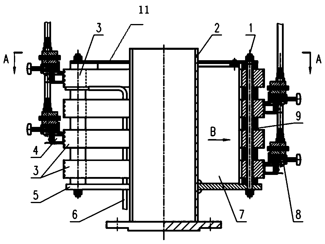
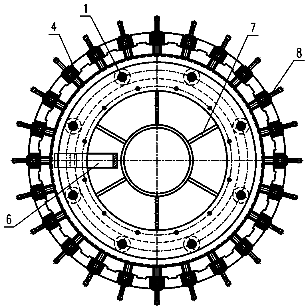
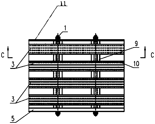
[0028] This embodiment includes three collector rings 3, a rotating shaft 2, six rib plates 7, a lower support plate 5 and an upper splint 11, a tension bolt 1, an insulating spacer 9, a carbon brush 5, a brush holder 8 and a flow guide copper The row 6 and the rib plate 7 are welded on the rotating shaft 2, the plurality of collector rings 3 are axially concentric (the centers of each collector ring are on the same axis), and the axial weight is borne by the lower support ring plate 11. After the tension bolt 1 is covered with an insulating sleeve, it passes through the upper splint 11, the insulating spacer 9, the collector ring 3 and the lower support plate, and the upper splint 11, the insulating spacer 9, the collector ring 3 and the lower support plate 5 are connected as a whole, and there is a gap between each collector ring 3, and the distance of the gap is the same, and the tension bolt 1 and the collector ring 3 realize insulating contact through an insulating sleeve....
Embodiment 2
[0034] This embodiment includes four collector rings 3, rotating shaft 2, four rib plates 7, lower support plate 5 and upper splint 11, tension bolt 1, insulating spacer 9, carbon brush 5, brush holder 8 and diversion copper The row 6 and the rib plate 7 are welded on the rotating shaft 2, the plurality of collector rings 3 are axially concentric (the centers of each collector ring are on the same axis), and the axial weight is borne by the lower support ring plate 11. The tension bolt 1 and the screw part of the collector ring foundation are wound with an insulating material layer and pass through the upper splint 11, the insulating spacer 9, the collector ring 3 and the lower support plate, and the upper splint 11, the insulating spacer 9, The collector rings 3 and the lower support plate 5 are connected as a whole, and gaps are provided between each collector ring 3 , and the gap distances are the same. The tension bolt 1 and the collector ring 3 are insulated and contacted ...
Embodiment 3
[0040] This embodiment includes five collector rings 3, a rotating shaft 2, three rib plates 7, a lower support plate 5, an upper splint 11, a tension bolt 1, an insulating spacer 9, a carbon brush 5, a brush holder 8 and a flow guide copper The row 6 and the rib plate 7 are welded on the rotating shaft 2, the plurality of collector rings 3 are axially concentric (the centers of each collector ring are on the same axis), and the axial weight is borne by the lower support ring plate 11. After the tension bolt 1 is covered with an insulating sleeve, it passes through the upper splint 11, the insulating spacer 9, the collector ring 3 and the lower support plate, and the upper splint 11, the insulating spacer 9, the collector ring 3 and the lower support plate 5 are connected as a whole, and there is a gap between each collector ring 3, and the distance of the gap is the same, and the tension bolt 1 and the collector ring 3 realize insulating contact through an insulating sleeve. ...
PUM
 Abstract
Description
Claims
Application Information
 - R&D
- Intellectual Property
- Life Sciences
- Materials
- Tech Scout
- Unparalleled Data Quality
- Higher Quality Content
- 60% Fewer Hallucinations
Browse by: Latest US Patents, China's latest patents, Technical Efficacy Thesaurus, Application Domain, Technology Topic, Popular Technical Reports.
© 2025 PatSnap. All rights reserved.Legal|Privacy policy|Modern Slavery Act Transparency Statement|Sitemap|About US| Contact US: help@patsnap.com