
Performance detecting method and system of radio frequency terminal

A detection method and detection system technology, applied in transmission systems, digital transmission systems, transmitter monitoring, etc., can solve problems such as difficult debugging and precise positioning, and achieve the effect of improving overall performance

Active Publication Date: 2015-12-16
湖州帷幄知识产权运营有限公司
View PDF6 Cites 12 Cited by
  • Summary
  • Abstract
  • Description
  • Claims
  • Application Information

AI Technical Summary

Problems solved by technology

[0004] In view of the above-mentioned shortcomings of the prior art, the purpose of the present invention is to provide a radio frequency terminal performance testing method and system, which are used to solve the problem that it is difficult to accurately locate the cause of the problem and difficult to debug in the existing radio frequency performance testing technology

Method used


Image

  • Performance detecting method and system of radio frequency terminal
  • Performance detecting method and system of radio frequency terminal
  • Performance detecting method and system of radio frequency terminal

Examples


Embodiment Construction

[0033] Embodiments of the present invention are described below through specific examples, and those skilled in the art can easily understand other advantages and effects of the present invention from the content disclosed in this specification. The present invention can also be implemented or applied through other different specific implementation modes, and various modifications or changes can be made to the details in this specification based on different viewpoints and applications without departing from the spirit of the present invention. It should be noted that, in the case of no conflict, the following embodiments and features in the embodiments can be combined with each other.

[0034] It should be noted that the diagrams provided in the following embodiments are only schematically illustrating the basic ideas of the present invention, and only the components related to the present invention are shown in the diagrams rather than the number, shape and shape of the compo...


PUM


Abstract

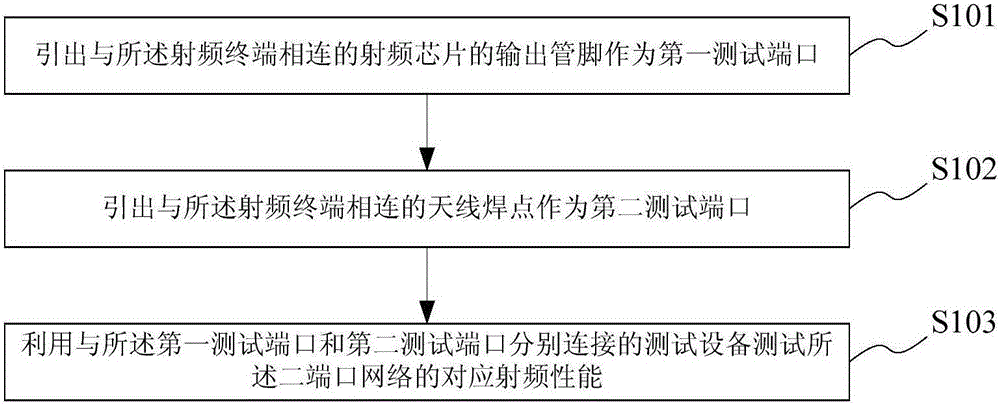
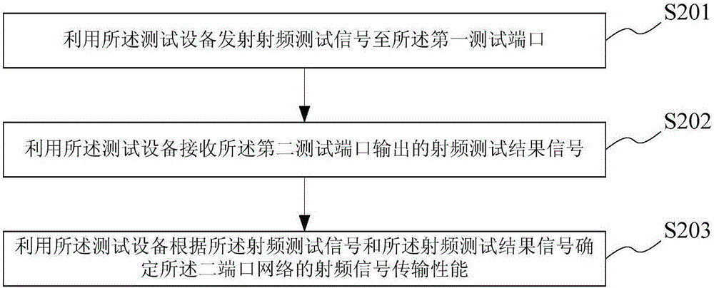
The invention provides a performance detecting method and system of a radio frequency terminal. The performance detecting method of the radio frequency terminal comprises steps of: using the output pin, connected with the radio frequency terminal, of a radio frequency chip as a first testing port; using an antenna solder joint connected with the radio frequency terminal as a second testing port, wherein the first testing port, the radio frequency chip, the radio frequency terminal, and the antenna solder joint form a two-port network; and testing the corresponding radio frequency performance of the two-port network by using a testing device connected with the first testing port and the second testing port. The method may be independent of the radio frequency chip, directly detects and debugs the radio frequency terminal which is viewed as a two-port network, is compatible with more active and passive testing methods, modularly analyzes and solves radio frequency matching problems, and improves radio frequency output overall performance.

Description

technical field [0001] The invention belongs to the technical field of testing, and relates to a radio frequency performance testing method, in particular to a radio frequency terminal performance testing method and system. Background technique [0002] The radio frequency debugging and testing method of conventional wireless routers generally uses radio frequency signal testing equipment to connect the radio frequency antenna solder joints of the wireless router to test its radio frequency input / output performance. In the test structure connection of the conventional test method, the radio frequency chip is connected to the radio frequency output terminal, the radio frequency output terminal is connected to the antenna solder joint, and the radio frequency signal test equipment is connected to the antenna solder joint through the radio frequency test line. This conventional test method can only test the RF signal at the RF output terminal, and at the same time relies on the...

Claims


Application Information

Patent Timeline
IPC IPC(8): H04L12/771H04L12/26H04B17/15H04B17/29H04L45/60
Inventor 徐沈骏薄轶祥
Owner 湖州帷幄知识产权运营有限公司
Learn More