A fin assembly long U-shaped tube automatic intubation system and its application method

A U-shaped tube and fin technology, which is applied in the field of air conditioner manufacturing, can solve the problems of not being able to work at the same time, affecting the production progress, and low intubation efficiency.

Active Publication Date: 2019-04-30
XUZHOU DKEC ELECTRICAL TECH
View PDF9 Cites 0 Cited by
  • Summary
  • Abstract
  • Description
  • Claims
  • Application Information

AI Technical Summary

Problems solved by technology

[0008] 1. Since the intubation operation is performed manually, human factors such as the operator's sense of responsibility and emotion have a greater impact on the production progress, and because the front stamping fin process and copper tube bending process are all mechanically operated, the efficiency is relatively high Therefore, in order to meet the normal progress of the follow-up tube expansion process, it is often necessary to set up multiple people to manually insert and lengthen the U-shaped tube process at the same time. The accumulation of too much output, the subsequent process shutdown and waiting for materials, the equipment automation degree is low, the equipment utilization rate is low, and the production capacity cannot be guaranteed;
[0009] 2. Since the intubation process is manual, it requires high skills and proficiency of the operators. The uneven operation proficiency of multiple operators also affects the production progress to varying degrees, and easily leads to unstable product quality ;
[0010] 3. The existing automatic intubation system is a long U-shaped tube that is horizontally inserted horizontally and arranged side by side or placed vertically. Since the long U-shaped tube is usually long, the insertion of the horizontally placed long U-shaped tube Due to the influence of the long U-shaped tube's own gravity or placement factors, the method cannot guarantee absolute accuracy in inserting into the insertion hole of the fin group, which usually causes friction between the fin group and the long U-shaped tube during the intubation process, or even Damage to the fins; and the fin grabbing unit, U-shaped tube grabbing unit and intubation unit usually work in sequence, there is work interference between them, and they cannot work at the same time. It is necessary to complete a workflow before proceeding to the next job Flow, the work can not be interspersed, resulting in intubation efficiency is not high

Method used


Image

  • A fin assembly long U-shaped tube automatic intubation system and its application method
  • A fin assembly long U-shaped tube automatic intubation system and its application method
  • A fin assembly long U-shaped tube automatic intubation system and its application method

Examples


Embodiment Construction

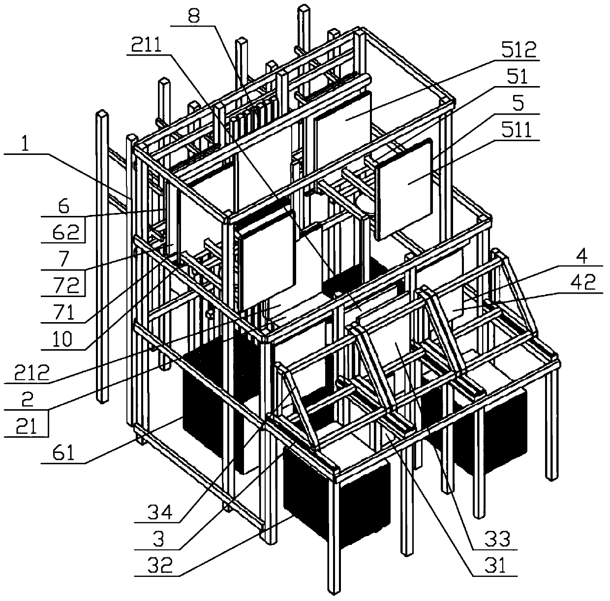
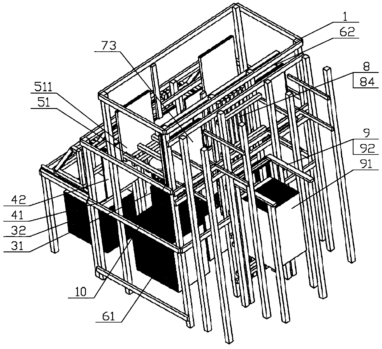
[0073] The present invention will be further described below in conjunction with the accompanying drawings (the following description takes the direction where the fin assembly grabbing and stacking unit 3 is located in the fin assembly long U-shaped tube automatic intubation system as the front).

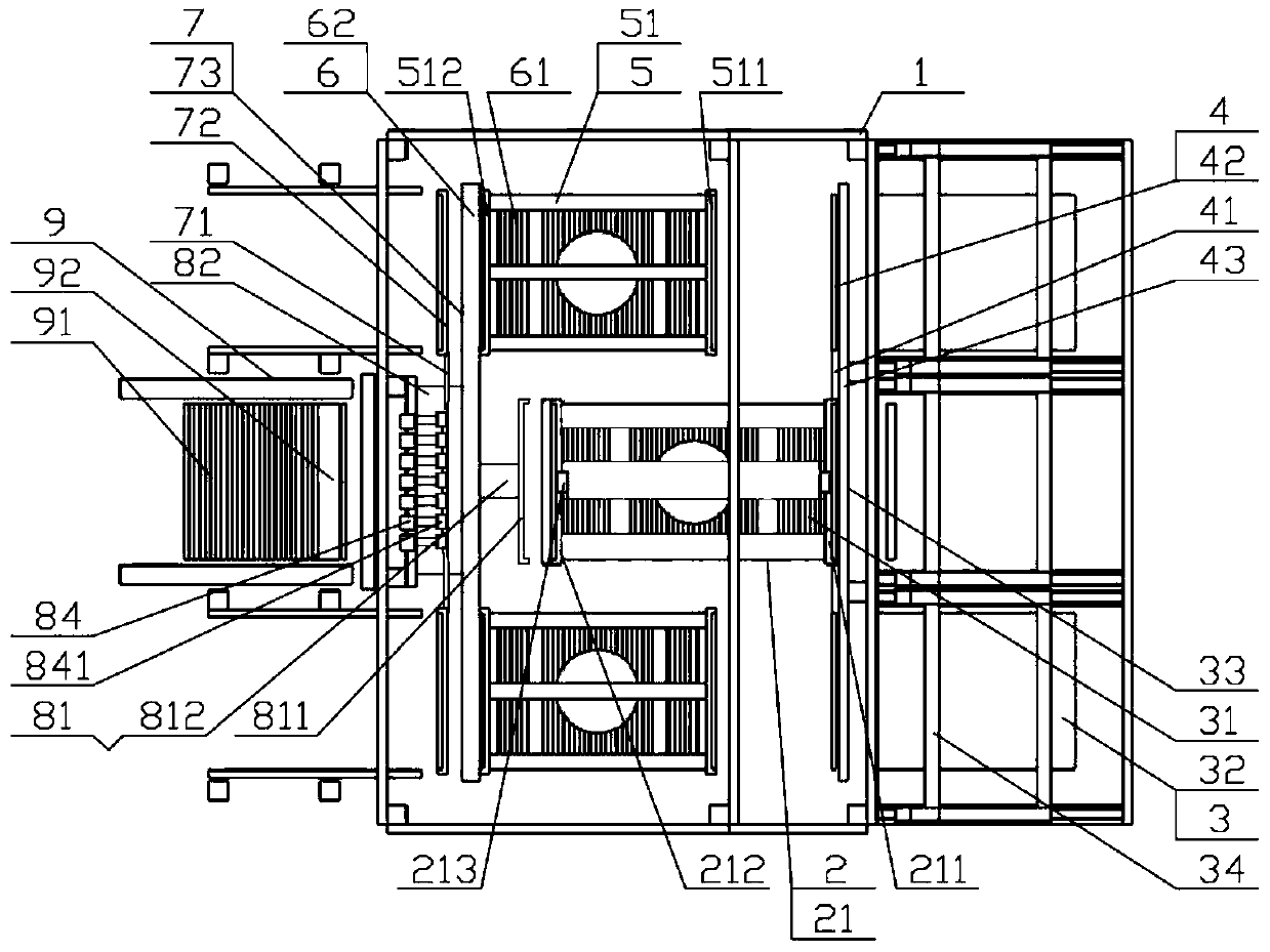
[0074] Such as Figure 1 to Figure 4 As shown, the fin assembly long U-shaped tube automatic intubation system is set as an upper, middle, and lower three-layer structure, including a support frame 1, a fin assembly accompanying tooling transposition work unit 2, and a fin assembly grasping and stacking Unit 3, fin assembly accompanying tooling unit 4, U-shaped tube accompanying tooling indexing unit 5, U-shaped tube grabbing unit 6, U-shaped tube accompanying tooling unit 7, intubation unit 8, supporting steel plate grabbing and stacking unit 9 and the electronic control unit.

[0075] The fin assembly accompanying tool indexing working unit 2 is arranged in the middle layer of t...


PUM


Abstract

The invention discloses an automatic fin assembly long U-pipe insertion system and a use method thereof. A support frame (1) of the system is of a three-layer structure comprising an upper layer, a middle layer and a lower layer; the system comprises a fin assembly accompanying tool transposition work unit (2), fin assembly grabbing and stacking units (3), a fin assembly accompanying tool unit (4), U-pipe accompanying tool transposition work units (5), a U-pipe grabbing unit (6), a U-pipe accompanying tool unit (7), a pipe insertion unit (8) and a support steel plate grabbing and stacking unit (9). All units of the system are arranged at different layers; all units can work simultaneously, so that the production efficiency is high; the positions of the fin assembly accompanying tool unit (4) and U-pipe accompanying tools (72) can be changed according to work requirements; the rotation timing of a fin assembly accompanying tool rotation workbench and a U-pipe accompanying tool rotation workbench is reasonably set to avoid the material lack stop state of the pipe insertion unit, so that efficient pipe insertion can be realized; and the automatic fin assembly long U-pipe insertion system is suitable for a digitized condenser and evaporator factory.

Description

technical field [0001] The invention relates to a fin assembly automatic intubation system, in particular to a fin assembly long U-shaped tube automatic intubation system suitable for the fin assembly long U-shaped tube intubation process of radiators and condensers of air conditioners , belongs to the technical field of air conditioner manufacturing. Background technique [0002] Usually, metal sheets with strong thermal conductivity are added on the surface of the heat exchange device that requires heat transfer to increase the heat exchange surface area of ​​the heat exchange device and improve the heat exchange efficiency. The metal sheets with this function are called fins. [0003] There are two main heat exchangers in the air conditioner, namely the radiator and the condenser. The working medium of these two heat exchangers is refrigerant on one side and air on the other side. In order to enhance the heat transfer of the heat exchanger, generally The heat exchange ar...

Claims


Application Information

Patent Timeline
Patent Type & Authority Patents(China)
IPC IPC(8): B23P19/00
CPCB23P19/00
Inventor 郝新浦
Owner XUZHOU DKEC ELECTRICAL TECH
Why Eureka
Try Eureka