Die structure

A mold and mold base technology, applied in the field of mold structure, can solve problems such as poor product air trapping, block exhaust gaps, and reduce production efficiency, and achieve the effects of improving the quality of injection molding products, facilitating operation, and improving production efficiency.

Active Publication Date: 2015-12-23
UNION OPTECH
View PDF4 Cites 4 Cited by
  • Summary
  • Abstract
  • Description
  • Claims
  • Application Information

AI Technical Summary

Problems solved by technology

[0003] For precision products, in order to ensure the stability of the product size, the exhaust of the mold must be considered on the mold. The solution to the poor exhaust is to make inserts. The traditional inserts are fixed. This method only It can correspond to small batch production. If mass production is required, gas gas will be generated during the plastic injection molding process. This gas will block the exhaust gap between the inserts and cause defective products, because the core inserts are fixed. , It is impossible to clean it directly on the injection molding machine. At this time, the mold can only be lowered and completely disassembled for cleaning and maintenance. After the mold is installed, it will be restarted for production. Repeated operations will greatly reduce production efficiency.
[0004] like Figure 5 As shown, in the mold structure of the non-movable mold core, after the mold is opened, the product A is ejected from the lower mold core 5 under the action of the thimble 21, and the gas gas generated during the injection molding process will block the mold after hundreds of thousands of molds are produced. The exhaust gap between the central core 31 and the lower mold core 5 will cause poor air trapping in the product. At this time, you can only disassemble the mold after getting off the machine for cleaning and then put it on the machine

Method used


Image

  • Die structure
  • Die structure
  • Die structure

Examples


Embodiment Construction

[0023] The present invention will be described in further detail below in conjunction with the accompanying drawings.

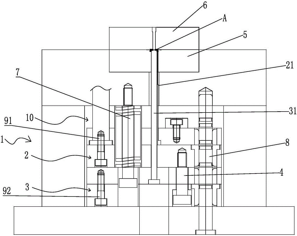
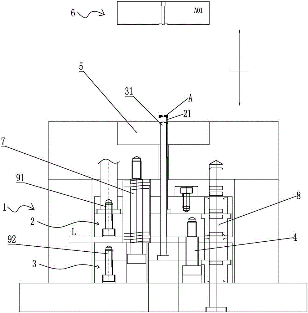
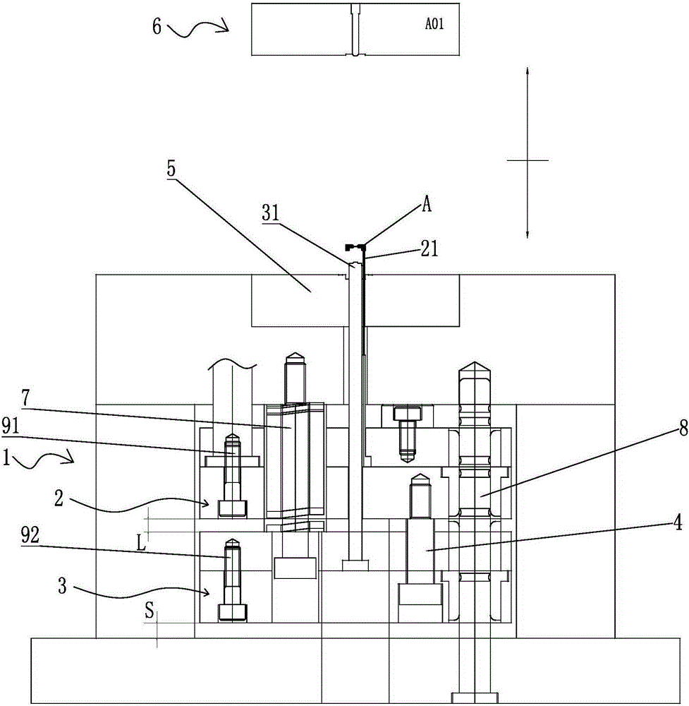
[0024] Such as Figure 1 to Figure 4 Shown, a kind of mold structure comprises formwork 1, is provided with cavity 10 in described formwork 1, is provided with the opening 11 that communicates with described cavity 10 on described formwork 1, in described cavity A first ejector plate 2 and a second ejector plate 3 are provided in the cavity 10, and a central core 31 is arranged on the second ejector plate 3, and the central core 31 passes through the first ejector plate 2 and the opening 11 extending to the upper surface of the mold base 1, and the ejector pin 21 for ejecting the molded product at the top of the central core 31 is arranged on the first ejector plate 2, and on the first ejector plate 2 2 and the second ejector plate 3 are provided with a limit screw 4 for adjusting the position of the first ejector plate 2 and the second ejector plate 3, and ...


PUM


Abstract

The invention relates to a die structure comprising a die carrier, wherein a cavity is arranged in the die carrier; an opening communicated with the cavity is formed in the die carrier; the cavity is internally provided with a first ejector retainner plate and a second ejector retainner plate which are movable; the first ejector retainner plate is provided with a central die core which extends to the upper surface of the die carrier after passing through the first ejector retainner plate and the opening; the first ejector retainner plate is provided with an ejector pin for ejecting a molded product at the top end of the central die core; a limiting screw for regulating the positions of the first ejector retainner plate and the second ejector retainner plate is arranged between the first ejector retainner plate and the second ejector retainner plate; a lower die core is arranged at the outer side of the upper end of the central die core; and an upper die core is arranged on the lower die core. Through improving the die structure, the die core part can be directly cleaned and scrubbed on an injection molding machine, so that exhaust is kept smooth, the cleaning and maintaining frequency of a lower die is reduced, the production efficiency is increased, the cost is reduced, and the quality of an injection molded product is greatly improved.

Description

【Technical field】 [0001] The invention relates to a mold structure. 【Background technique】 [0002] Mold, various molds and tools used in industrial production for injection molding, blow molding, extrusion, die-casting or forging forming, smelting, stamping and other methods to obtain the required products. In short, molds are tools used to shape objects. This tool is composed of various parts, and different molds are composed of different parts. It mainly realizes the processing of the shape of the object through the change of the physical state of the formed material. [0003] For precision products, in order to ensure the stability of the product size, the exhaust of the mold must be considered on the mold. The solution to the poor exhaust is to make inserts. The traditional inserts are fixed. This method only It can correspond to small batch production. If mass production is required, gas gas will be generated during the plastic injection molding process. This gas will...

Claims


Application Information

Patent Timeline
Patent Type & Authority Applications(China)
IPC IPC(8): B29C45/26B29C45/36B29C45/40
CPCB29C45/2602B29C45/4005B29C2045/363
Inventor 曾庆援李映强杨勇陈远财葛承尹鸿林邓剑明彭清连邱盛平
Owner UNION OPTECH
Why Eureka
Try Eureka