A Method for Automatic Laying and Forming of Mesh Skin Structure with Local Concavity

A technology of automatic wire laying and forming method, which is applied in the field of automatic wire laying and forming, and can solve the problems of inability to automatically lay wires and the like.

Active Publication Date: 2017-07-07
AEROSPACE RES INST OF MATERIAL & PROCESSING TECH +1
View PDF6 Cites 0 Cited by
  • Summary
  • Abstract
  • Description
  • Claims
  • Application Information

AI Technical Summary

Problems solved by technology

[0005] The technical problem solved by the present invention is: to overcome the deficiencies of the prior art, to provide an automatic wire laying forming method for a grid skin structure with local depressions, to solve the technical problem that automatic laying of wires cannot be performed in the depressions, and to realize automatic wire laying. Application of Wire Laying Technology in Typical Structures of Composite Materials

Method used


Image

  • A Method for Automatic Laying and Forming of Mesh Skin Structure with Local Concavity
  • A Method for Automatic Laying and Forming of Mesh Skin Structure with Local Concavity
  • A Method for Automatic Laying and Forming of Mesh Skin Structure with Local Concavity

Examples


Embodiment 1

[0056] Example 1: Forming of a grid-skinned structure with vertical end frames

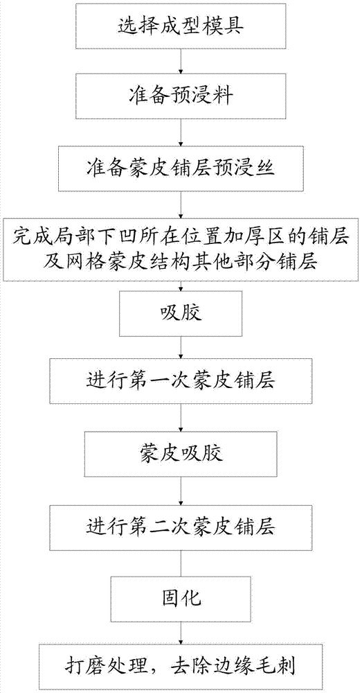
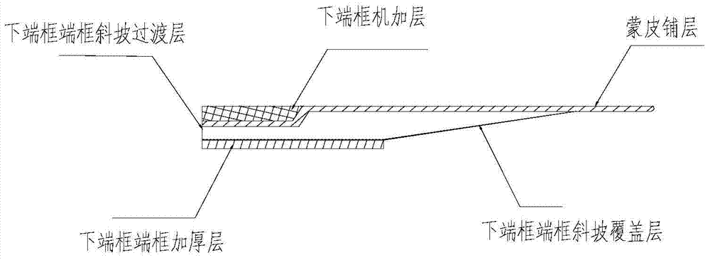
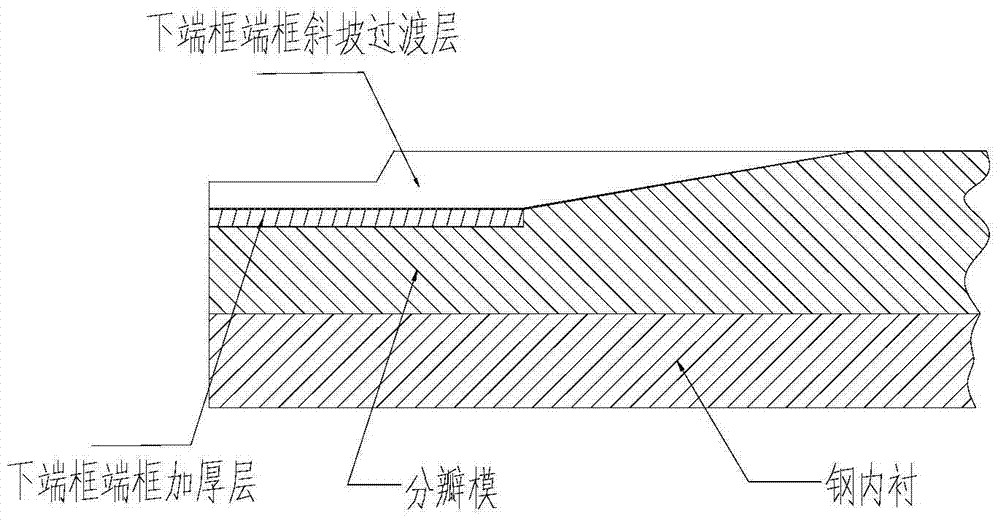
[0057] Vertical end frame forming requirements: The lower end frame of the component is a vertical end frame structure. In order to keep the skin layup continuous, the layup plan is modified at the thinned part of the lower end frame, and the thickened layup of the end frame is deleted. The thickness is reduced from 18.5mm to 11.5mm along the R8 arc. Such as figure 2 Shown is a schematic diagram of the layup of the lower end frame skin, reinforcement areas and ribs.

[0058] Due to the large thickness of the vertical end frame and the thickening area, it is necessary to lay the hot-melt prepreg into 5-7 layers of blocks first, enter the oven to pre-absorb the glue, and then carry out the block cutting and cutting according to the required size. Lamination, autoclave suction glue.

[0059] When the vertical end frame covers the suction glue, the upper and lower end rings need to be installed, a...

Embodiment 2

[0089] Embodiment 2: Forming of mesh skin structure with window

[0090] Window forming requirements: The window reinforcement area is formed directly instead of being processed after the product is cured. Its thickness is 20mm and is sharply reduced to 10mm at the edge of the window. The edge is different from the edge of the vertical end frame, and the edge of the laminate needs to be perpendicular to the skin. Such as Figure 8 Shown is a schematic diagram of the structure of the window reinforcement area.

[0091] (1) Forming mold preparation

[0092] Install the mold assembly, the process extension ring is not installed temporarily, clean the surface of the mold, and apply a release agent.

[0093] (2) Prepreg blanking

[0094] Prepreg by hot melt method. According to the three-dimensional digital model of the product, through conversion, the precise technology of the layer size in the window area is carried out, and the automatic blanking equipment is used for precis...


PUM

PropertyMeasurementUnit
thicknessaaaaaaaaaa

Abstract

The invention discloses an automatic fiber placement forming method for a grid skin structure with a part concave structure. The method comprises the following steps that a forming mold is selected; material is presoaked with the adoption of a hot melting method; presoaked fibers are prepared; placement in the thickened area of the part concave position and placement for other parts of a grid shell body are completed with the aid of hands by using the presoaked material; glue absorption is conducted in a hot-pressing pot; a first skin placement is conducted; skin glue absorption is conducted in the hot-pressing pot; a second skin placement is conducted; solidification is conducted; and polishing treatment is conducted, and automatic fiber placement forming for the grid skin structure with the part concave structure is completed. According to the method, the technical problem that automatic fiber placement can not be conducted in the concave position is solved, and the application of an automatic fiber placement technique on a composite typical structure component is achieved.

Description

technical field [0001] The invention relates to an automatic wire laying molding method, belonging to composite material molding technology. Background technique [0002] Foreign countries have widely used automatic molding technology in composite skin component products, which is typically represented by automatic wire laying technology. The automatic wire laying technology is to use a multi-axis laying head (robot) to collect several prepregs into a ribbon under the pressure roller according to the laying direction determined by the design requirements, and then lay it on the surface of the mandrel for compaction and shaping. The whole process is completed by computer measurement, control and coordination system. [0003] The automatic wire laying technology combines the advantages of fiber winding and automatic tape laying technology. It can cut the tow at any time according to the change of the surface shape of the component, and continue to transport the tow when neces...

Claims


Application Information

Patent Timeline
Patent Type & Authority Patents(China)
IPC IPC(8): B29C70/34B29C70/38B29C70/44
CPCB29C70/342B29C70/382B29C70/386B29C70/44
Inventor 张建宝赵文宇孙文文
Owner AEROSPACE RES INST OF MATERIAL & PROCESSING TECH
Why Eureka
Try Eureka