Radiating fin structure surface-mount rectifier bridge device

A technology of structural surface and rectifier bridge, which is applied in the direction of electric solid-state devices, semiconductor devices, semiconductor/solid-state device components, etc., can solve the problems of large PCB board space, unfavorable energy saving and environmental protection, and large thickness, and achieve the effect of superior thermal conductivity

Active Publication Date: 2015-12-23
SUZHOU GOODARK ELECTRONICS CO LTD
View PDF6 Cites 3 Cited by
  • Summary
  • Abstract
  • Description
  • Claims
  • Application Information

AI Technical Summary

Problems solved by technology

To sum up, the existing technology has the disadvantages that the product has a large thickness and takes up a large space on the PCB board, which is not suitable for the miniaturization of the terminal product; the heat dissipation performance of the product is not good, resulting in a large heat generation of the terminal product, which is not conducive to energy saving and environmental protection; the reflow soldering method is not suitable Soldering, when other products on the PCB board need to be soldered by reflow soldering, the entire PCB board needs to be heated twice, which will cause technical problems such as damage to the assembled devices

Method used


Image

  • Radiating fin structure surface-mount rectifier bridge device
  • Radiating fin structure surface-mount rectifier bridge device
  • Radiating fin structure surface-mount rectifier bridge device

Examples


Embodiment

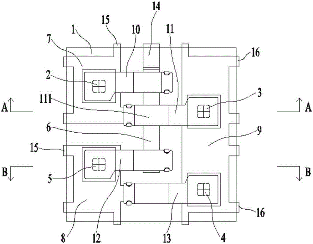
[0026] Embodiment: A heat sink structure surface mount rectifier bridge device, including: first, second, third, fourth diode chips 2, 3, 4, 5 and negative electrodes covered by epoxy package 1 Metal strip 6, the bottom of the epoxy package 1 and the first and second metal substrates 7, 8 and E-shaped metal substrate 9 are respectively fixed on the left and right sides, and the negative electrode metal strip 6 is located on the first, second, and second metal substrates. Between the second metal substrate 7,8 and the E-shaped metal substrate 9;

[0027] The positive terminal of the first diode chip 2 is electrically connected with the upper surface of the first metal substrate 7, the negative terminal of the second diode chip 3 is electrically connected with the upper surface of one end of the E-shaped metal substrate 9, and the third diode The negative end of the chip 4 is electrically connected to the upper surface of the other end of the E-shaped metal substrate 9, and the ...


PUM


Abstract

The invention discloses a radiating fin structure surface-mount rectifier bridge device. The radiating fin structure surface-mount rectifier bridge device comprises a first diode chip, a second diode chip, a third diode chip, a fourth diode chip and a cathode metal strip all coated by an epoxy packaging body, and a first metal substrate, a second metal substrate and an E-shaped metal substrate are respectively located at left side and right side of the bottom of the epoxy packaging body; a first connecting sheet, a second connecting sheet, a third connecting sheet and a fourth connecting sheet are arranged in parallel along a front-to-back direction; the front end of the cathode metal strip, located between the first metal substrate and the E-shaped metal substrate, comprises a bending part, and the bottom of the bending part and the bottom of each of the first metal substrate, the second meal substrate and the E-shaped metal substrate are in the same horizontal plane and are all naked outside the epoxy packaging body; the first metal substrate and the second metal substrate are used as alternating current input ends, the cathode metal strip is used as a direct current cathode end, and the E-shaped metal substrate is used as a direct current anode end. According to the invention, a radiating path between the chips and a PCB is shortest, radiating fins are metal material and have excellent heat conductivity coefficient, own radiating capacity of the PCB is used fully, and defects of the existing product, such as poor epoxy heat conduction capability caused by radiating through air convection in a case, are avoided.

Description

technical field [0001] The invention relates to a rectifying semiconductor device, in particular to a rectifying bridge device mounted on the surface of a heat sink structure. Background technique [0002] The rectifier is a bridge structure composed of four rectifying diodes. It uses the unidirectional conduction characteristics of the diodes to rectify the alternating current. Since the utilization efficiency of the bridge rectifier for the input sine wave is twice as high as that of the wave rectification, it is half of the diode. It is a significant improvement of wave rectification, so it is widely used in circuits that convert alternating current into direct current. [0003] On the one hand, the existing double-row laminated structure rectifier has a simple production process and is easy to operate. However, the flatness of the support sheet where each diode grain is located affects each other, resulting in unstable internal stress conditions during the production pr...

Claims


Application Information

Patent Timeline
Patent Type & Authority Applications(China)
IPC IPC(8): H01L23/31H01L23/367H01L25/07
CPCH01L2924/00014H01L2924/181H01L2224/40245H01L2924/00012H01L2224/37099
Inventor 张雄杰何洪运程琳
Owner SUZHOU GOODARK ELECTRONICS CO LTD
Why Eureka
Try Eureka