
Device and method for relieving negative pressure of long nozzle and impact force of molten steel

A long nozzle and impact force technology, which is applied in the direction of casting molten material containers, metal processing equipment, casting equipment, etc., can solve the problems of large size, high maintenance and operation costs, and achieve the goals of increasing service life, reducing impact force, and slowing down negative pressure Effect

Inactive Publication Date: 2015-12-30
ANGANG STEEL CO LTD
View PDF9 Cites 0 Cited by
  • Summary
  • Abstract
  • Description
  • Claims
  • Application Information

AI Technical Summary

Problems solved by technology

Mold electromagnetic braking technology can restrain the flow of molten steel and reduce the impact depth, but this equipment is generally added outside the mold, which is relatively large, and the maintenance and operation costs are also high

Method used

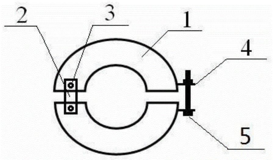
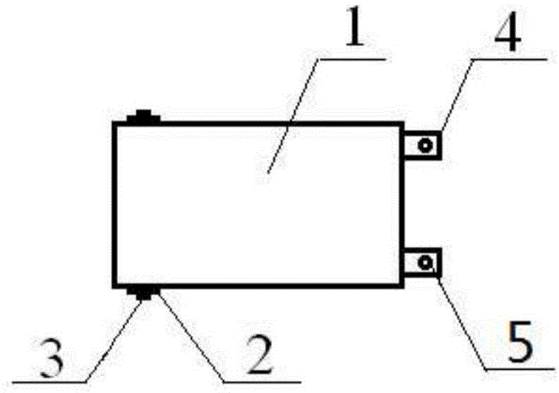
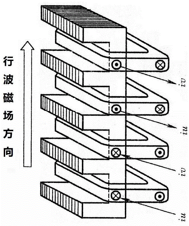

Image

  • Device and method for relieving negative pressure of long nozzle and impact force of molten steel
  • Device and method for relieving negative pressure of long nozzle and impact force of molten steel
  • Device and method for relieving negative pressure of long nozzle and impact force of molten steel

Examples


Embodiment 1

[0023] In the continuous casting process of 230×1060mm slab, the outer diameter of the shroud is Φ155mm, the inner diameter is Φ100mm and the casting speed is 0.8m / min.

[0024] Table 1. Device parameters when the outer diameter of the shroud is Φ155mm

[0025]

[0026] During use, the housing 1 of the magnetic field generating device is installed on the shroud 7 . Because the device needs to be cooled by water, in order to prevent the temperature from dropping too fast near the long nozzle, it can be protected by refractory felt or other heat-insulating and high-temperature-resistant materials. Set the current size and frequency of the device before starting casting. Turn on the power of the device when casting, and disconnect the power when the casting is over. The cooling water needs to be kept on to ensure that the device will not be burned out. The cooling water of the device can only be disconnected when the ambient temperature is low. Example 2:

Embodiment 2

[0027] In the continuous casting process of 300×1950mm slab, the outer diameter of shroud is Φ195mm, the inner diameter is Φ135mm, and the casting speed is 1.0m / min, the specific parameters of the device designed to slow down the negative pressure of shroud nozzle and the impact force of molten steel are shown in Table 2 .

[0028] Table 2. Device parameters when the outer diameter of the shroud is Φ195mm

[0029]

[0030] The application method is the same as in Example 1. The implementation effect is shown in Table 3. ON indicates the working state of the device, and OFF indicates the closed state of the device. From the experimental results in Table 3, it can be seen that the oxygen content of the tundish does not increase significantly under the working state of the device, indicating that the device effectively slows down the secondary oxidation of molten steel in the tundish caused by negative pressure at the nozzle.

[0031] Table 3 Comparison of pouring test resul...


PUM


Abstract

The invention discloses a device and method for relieving negative pressure of a long nozzle and impact force of molten steel. When the molten steel enters a tundish from a steel ladle through the long nozzle, a magnetic field generating device is additionally arranged on the outer wall of the long nozzle, currents of the magnetic field generating device are 2-200 A, and frequency is 1-10 Hz. The magnetic field generating device comprises a pair of semicircular shells, one ends of the semicircular shells are connected through a connecting plate, and the other ends of the semicircular shells are connected through a fastening plate and a fastening bolt. The two ends of the connecting plate are fixed to the surfaces of the two semicircular shells through fixing bolts respectively. The interior of each shell is formed by winding a coil around an iron core, wherein the coil is a copper tube, and water is introduced to cool the tube or a copper wire soaked with insulating varnish is adopted to serve as the exterior of the coil for introducing and cooling water. A two-phase or three-phase power source is adopted in the device for power supply.

Description

technical field [0001] The invention relates to a ladle casting shroud and electromagnetic flow control technology, in particular to a device and method for slowing down the negative pressure of the shroud and the impact force of molten steel. Background technique [0002] The shroud is a transitional device connecting the ladle and the tundish, and is an indispensable part in steelmaking-continuous casting production. The molten steel in the ladle is injected into the tundish through the long nozzle to avoid secondary oxidation in the air, and the long nozzle plays an important role in protecting the pouring. However, in the case of bare pouring at the lower end of the nozzle, such as starting pouring and changing ladles, since the long nozzle is much longer than the submerged nozzle, the molten steel is getting faster and faster under the acceleration of gravity, and the contact area with the inner wall of the long nozzle is getting smaller and smaller, resulting in negati...

Claims


Application Information

Patent Timeline
Patent Type & Authority Applications(China)
IPC IPC(8): B22D41/50
Inventor 唐雪峰郭庆涛黄玉平贾吉祥廖相巍常桂华
Owner ANGANG STEEL CO LTD
Learn More