Mixing condensing system based on up-in-down-out superposed double-flow-path steam condenser

A mixed condensation and condenser technology, applied in steam/steam condensers, lighting and heating equipment, etc., can solve the problems of affecting the service life of the operation effect, cavitation of vacuum pumps, large steam content, etc., and improve thermal economy. , The effect of reducing the exhaust pressure of the turbine and the short main flow process

Inactive Publication Date: 2015-12-30
CENT SOUTHERN CHINA ELECTRIC POWER DESIGN INST CHINA POWER ENG CONSULTING GROUP CORP
View PDF6 Cites 2 Cited by
  • Summary
  • Abstract
  • Description
  • Claims
  • Application Information

AI Technical Summary

Problems solved by technology

The conventionally designed condensing system directly draws out the uncondensed steam and leaked air in the condenser through the vacuum pump. In this way, the steam-gas mixture entering the vacuum pump has a large steam content and high temperature, which is easy to cause cavitation of the vacuum pump and affect Operation effect and service life

Method used


Image

  • Mixing condensing system based on up-in-down-out superposed double-flow-path steam condenser
  • Mixing condensing system based on up-in-down-out superposed double-flow-path steam condenser
  • Mixing condensing system based on up-in-down-out superposed double-flow-path steam condenser

Examples


Embodiment Construction

[0025] The present invention will be further described in detail below in conjunction with the accompanying drawings and embodiments, but the embodiments should not be construed as limiting the present invention, but only as examples, and the advantages of the present invention will become clearer and easier to understand.

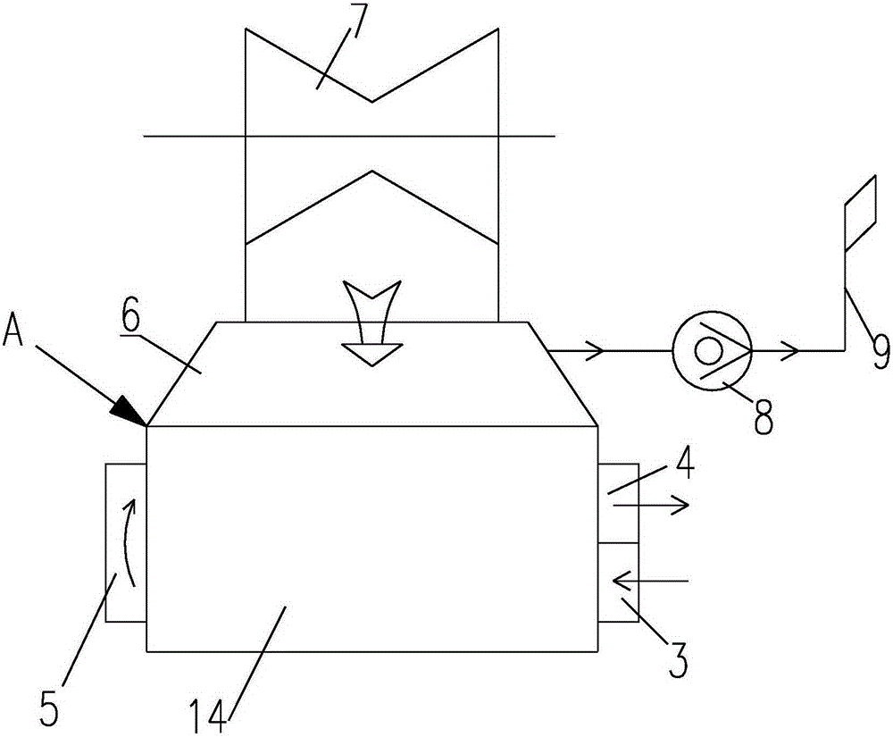
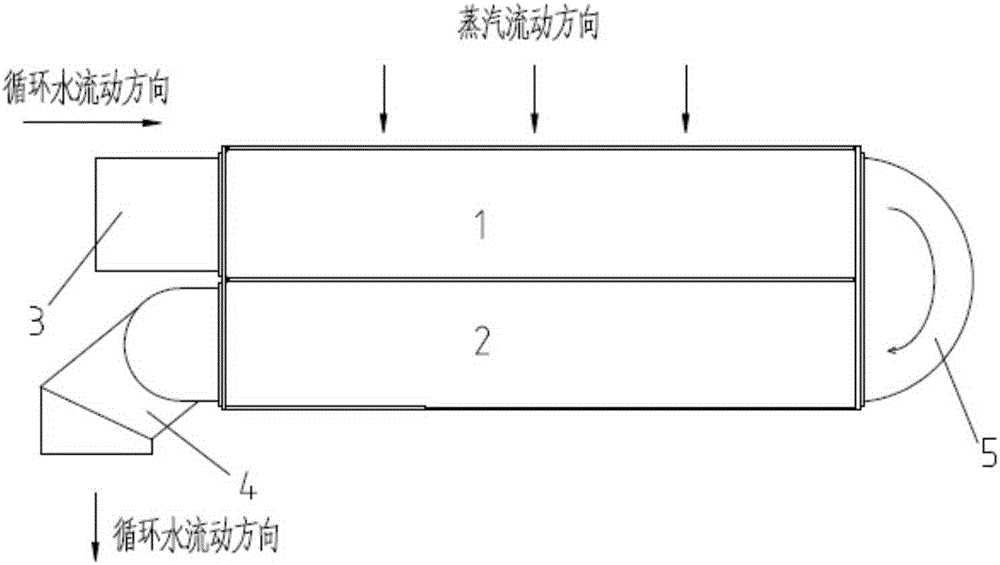
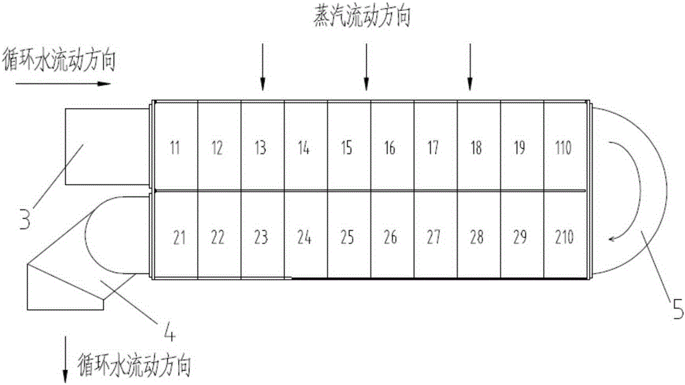
[0026] As shown in the figure, the hybrid condensing system based on stacked double-flow condensers with top in and bottom out includes condenser A. Condenser A includes a condenser heat exchange area 14, and the upper end of the condenser heat exchange area 14 is set There is a condenser throat 6, and the upper end of the condenser throat 6 is provided with a low-pressure cylinder 7; one side of the condenser heat exchange area 14 is provided with a rear water chamber 5, and the other side of the condenser heat exchange area 14 is provided with a circulation The cooling water inlet pipe 3 and the circulating cooling water outlet 4, the condenser heat excha...


PUM


Abstract

The invention discloses a mixing condensing system based on an up-in-down-out superposed double-flow-path steam condenser. The steam condenser is connected with an input end of a mixing condenser through an air extracting pipeline, and an output end of the mixing condenser is connected with the steam condenser through a condenser reflux pipeline and also connected with the condenser air extracting pipeline through a vacuum pump. A circulating water inlet is higher than a circulating water outlet. A first flow path pipe bundle region is positioned above a second flow path pipe bundle region. By adopting the single-back-pressure up-in-down-out superposed double-flow-path steam condenser (of which the first flow path pipe bundle region is above the second flow path pipe bundle region) and the mixing condensing system thereof, the mainstream flow path of the condenser exhaust steam is short, the flow resistance is small, the exhaust steam dynamic pressure can be converted into static pressure more easily, and the heat exchange effect is reinforced. More importantly, the channel width of the condenser exhaust steam flowing to the lower pipe bundle can be reduced, and the pipe bundle layout density can be increased to re-optimize the tube bundle arrangement, thereby lowering the height or width of the condenser pipe bundle region and lowering the condenser exhaust steam pressure.

Description

technical field [0001] The invention relates to circulating cooling water equipment for thermal power units, in particular it is a mixed condensing system based on stacked double-flow condensers entering from above and exiting from below. Background technique [0002] At present, when the circulating water process of the conventionally designed double-process surface condenser is bottom-in and top-out, the circulating water flows into the water inlet chamber, flows through the tube bundle of the first process to absorb the condensation and heat release of the exhaust steam of the turbine, and then flows into the rear water chamber, and then flow through the tube bundle of the second process to continue to absorb the heat release from the condensation of the exhaust steam of the turbine, and finally flow into the drainage chamber and exit the condenser. [0003] As we all know, the lower the temperature of the circulating water in the condenser, the greater the heat transfer ...

Claims


Application Information

Patent Timeline
Patent Type & Authority Applications(China)
IPC IPC(8): F28B1/02
Inventor 徐传海胡玉清匡云刘杰黄军军
Owner CENT SOUTHERN CHINA ELECTRIC POWER DESIGN INST CHINA POWER ENG CONSULTING GROUP CORP
Why Eureka
Try Eureka