

Thee-dimensional magnetic-induction magnetic compass
A magnetic compass and three-dimensional technology, applied in the field of magnetic compass, can solve the problems of lack of magnetic compass sensor technology
- Summary
- Abstract
- Description
- Claims
- Application Information
AI Technical Summary
Problems solved by technology
Method used
Image

Examples
specific Embodiment approach 1
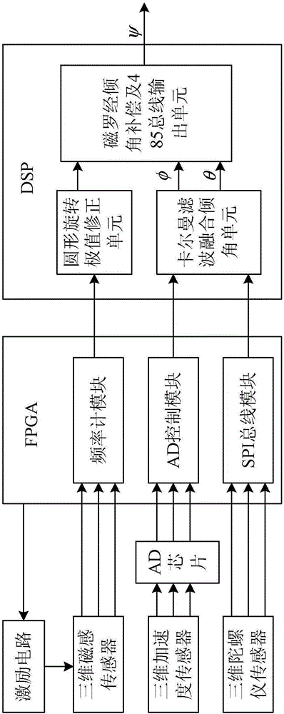
[0045] Specific implementation mode one: refer to figure 1 Describe this embodiment in detail, a kind of three-dimensional magnetic induction type magnetic compass described in this embodiment, it comprises: excitation circuit, three-dimensional magnetic induction sensor, three-dimensional acceleration sensor, three-dimensional gyroscope sensor, AD chip, FPGA and DSP;
[0046] FPGA includes: frequency meter module, AD control module and SPI bus module;
[0047] DSP includes: circular rotation extremum correction unit, Kalman filter fusion inclination unit, magnetic compass inclination compensation and 485 bus output unit;
[0048] The pulse signal output end of the excitation circuit is connected to the pulse signal input end of the three-dimensional magnetic induction sensor, the excitation direction control signal output end of the FPGA is connected to the excitation direction control signal input end of the excitation circuit, and the time difference signal output end of th...
specific Embodiment approach 2
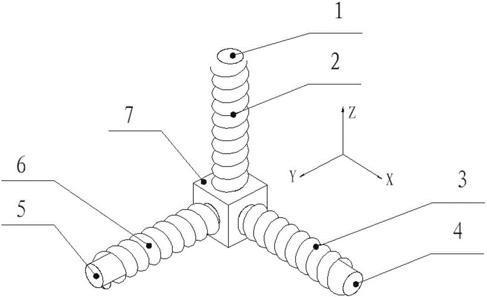
[0058] Specific implementation mode two: refer to figure 2 Describe this embodiment in detail. This embodiment is a further description of the three-dimensional magnetic induction magnetic compass described in the first embodiment. In this embodiment, the three-dimensional magnetic sensor includes: a Z-direction magnetic core 1, a Z-direction coil 2. X-direction coil 3, X-direction magnetic core 4, Y-direction magnetic core 5, Y-direction coil 6 and plastic base 7;
[0059] The plastic base 7 is a cube, and one end of the Z-direction magnetic core 1, one end of the X-direction magnetic core 4 and one end of the Y-direction magnetic core 5 are respectively fixed on three surfaces of the plastic base 7, and the three sides of the plastic base 7 Two planes are perpendicular to each other and adjacent to each other. The Z-direction coil 2 , the X-direction coil 3 and the Y-direction coil 6 are respectively wound on the Z-direction magnetic core 1 , the X-direction magnetic core 4...
specific Embodiment approach 3
[0065] Specific embodiment three: This embodiment is a further description of a three-dimensional magnetic induction magnetic compass described in specific embodiment two. In this embodiment, the Z-direction coil 2, the X-direction coil 3 and the Y-direction coil 6 are all 0.01mm enameled wire coil.
[0066] In this embodiment, the magnetic compass adopts Permalloy and enameled wire to make special inductors, and the three-dimensional structure adopts mold and integrated structure, which reduces the orthogonality error caused by assembly.
PUM
 Abstract
Description
Claims
Application Information