
Inversion method of sea surface wind field and apparatus thereof

A technology of sea surface wind field and sea surface wind speed, applied in the field of satellite navigation, can solve the problems of high wind direction ambiguity, inaccurate fitting, and large amount of calculation.

Inactive Publication Date: 2015-12-30
SPACE STAR TECH CO LTD
View PDF3 Cites 10 Cited by
  • Summary
  • Abstract
  • Description
  • Claims
  • Application Information

AI Technical Summary

Problems solved by technology

This inversion method has many limitations and deficiencies, such as large amount of calculation, high ambiguity of wind direction, and inaccurate fitting.

Method used


Image

  • Inversion method of sea surface wind field and apparatus thereof
  • Inversion method of sea surface wind field and apparatus thereof
  • Inversion method of sea surface wind field and apparatus thereof

Examples


Embodiment 1

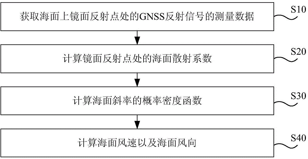
[0080] Such as figure 2 As shown, the flow chart of the inversion method for the sea surface wind field provided by an embodiment of the present invention, the method includes the following steps:

[0081] Step S10, the sea surface reflection receiver measures the GNSS signal (i.e. GNSS reflection signal) reflected at the mirror reflection point on the sea surface, obtains measurement data including power data, and preprocesses the acquired measurement data to obtain a smooth Measurement data;

[0082] In this embodiment, since the power data obtained by actual measurement is greatly affected by noise, it cannot be directly used for subsequent data calculation, so it is necessary to preprocess the measurement data, such as incoherent integration, filter noise reduction, normalization and other processing to obtain smooth scattered power measurement data and other measurement data;

[0083] Step S20, calculate the scattering coefficient at the specular reflection point based...

Embodiment 2

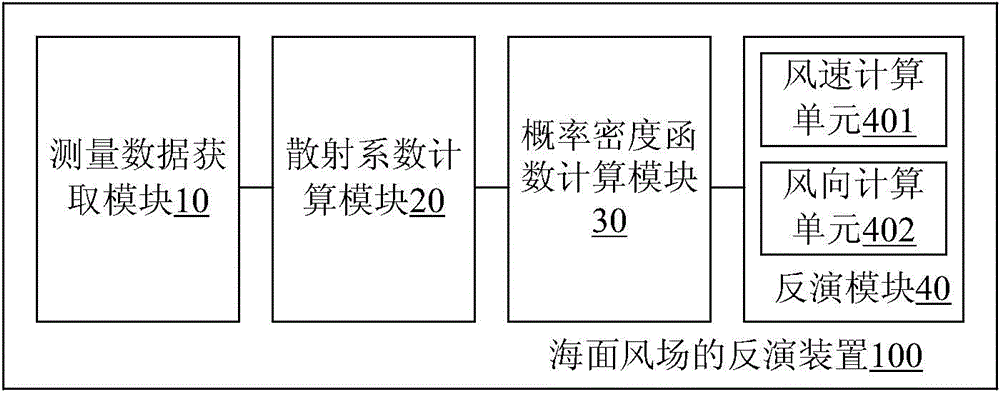
[0147] Such as image 3 As shown, it is a schematic structural diagram of an inversion device for a sea surface wind field provided by another embodiment of the present invention. The inversion device 100 for a sea surface wind field includes: a measurement data acquisition module 10, a scattering coefficient calculation module 20, a probability density function calculation module 30 and inversion module 40.

[0148] Wherein, the measurement data acquisition module 10 is used to obtain the measurement data of the GNSS reflection signal at the specular reflection point on the sea surface by means of beam control, and process the acquired measurement data to obtain smooth measurement data; the scattering coefficient calculation module 20 uses Based on the DDM power integral function expression obtained on the basis of the bistatic radar observation equation, the relationship between the measurement data of the GNSS reflected signal and the sea surface scattering coefficient is o...


PUM


Abstract

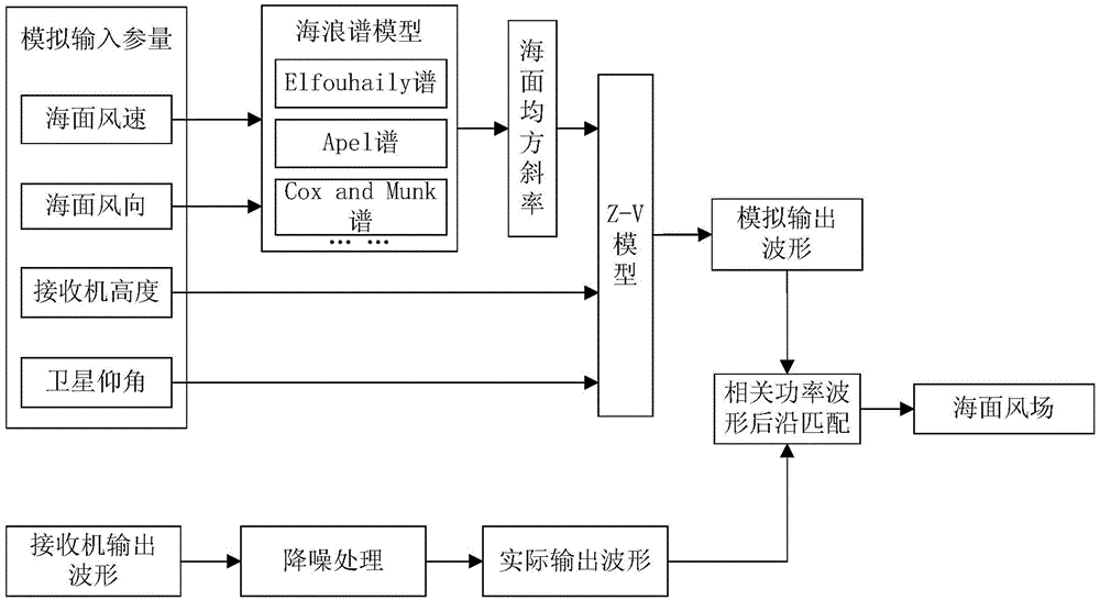
The invention discloses an inversion method of a sea surface wind field and an apparatus thereof. The method comprises the following steps of acquiring measurement data of a GNSS reflection signal at a specular reflection point on a sea surface and processing the measurement data so as to obtain smooth measurement data; based on a DDM power integration function expression obtained based on a double-base radar observation equation, acquiring a relation between the measurement data and a sea surface scattering coefficient, and calculating the sea surface scattering coefficient at the specular reflection point according to the relation and the smooth measurement data; based on a Z-V model, acquiring a relation between the sea surface scattering coefficient and a sea surface slope probability density function, and calculating a probability density function of a sea surface slope according to the calculated sea surface scattering coefficient and the relation between the sea surface scattering coefficient and the sea surface slope probability density function; according to the probability density function of the sea surface slope, calculating a sea surface wind speed and a wind direction. By using the method and the apparatus of the invention, a sea surface state can be rapidly and accurately inverted in real time.

Description

technical field [0001] The invention relates to the technical field of satellite navigation, in particular to a real-time and rapid inversion method and device for a spaceborne GNSS-R sea surface wind field. Background technique [0002] In recent years, with the deepening of the research on the Global Navigation Satellite System (GNSS), some scholars have found that the reflection signal of GNSS can be received and used outside the traditional satellite navigation field, thus opening up the A new research field, GNSS reflection (global navigation satellite system-reflection, GNSS-R) technology, the GNSS-R detection technology for studying the state of the earth's sea surface has thus developed into one of the new space detection technologies. The GNSS-R sea surface state detection technology is based on the principle that the GNSS signal is scattered by the sea surface when it is incident on the sea surface. Different sea surface states will have different effects on the sc...

Claims


Application Information

Patent Timeline
IPC IPC(8): G01S13/95
CPCY02A90/10
Inventor 李烨曲鹏程王烁金彪陈姗姗蔡仁澜
Owner SPACE STAR TECH CO LTD
Learn More