

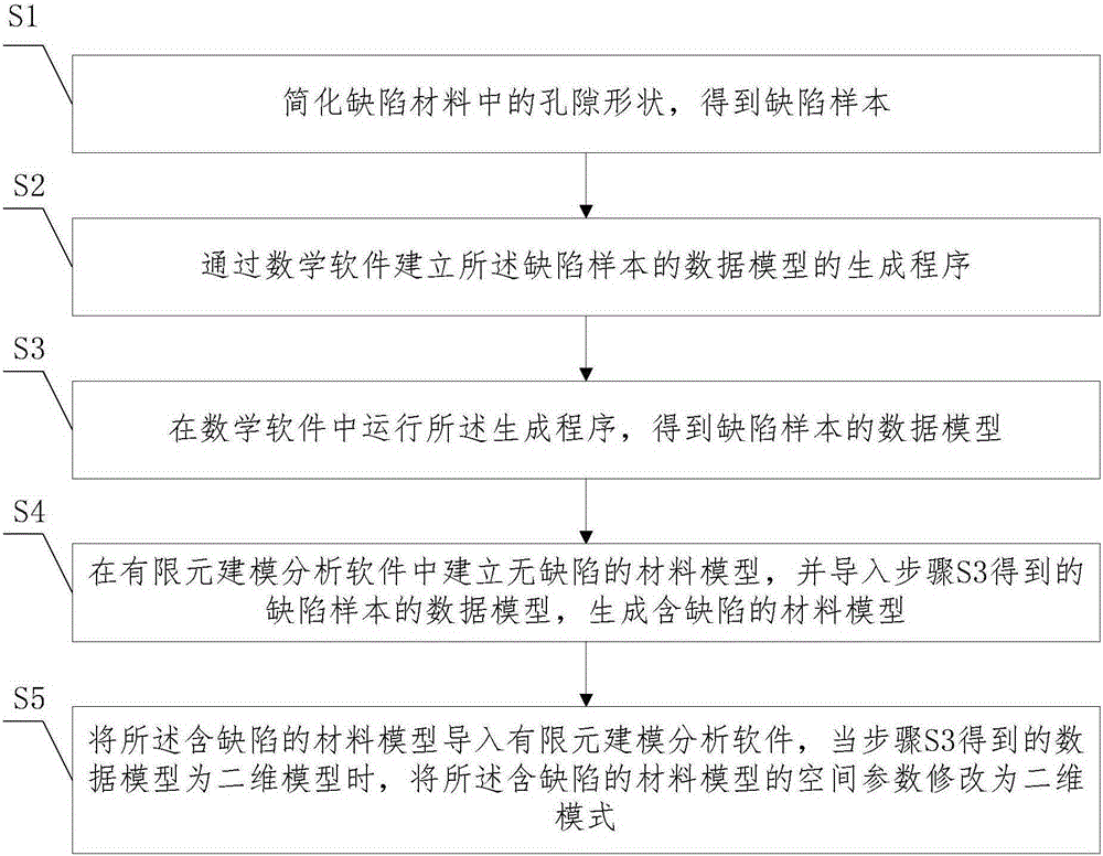
Finite element modeling method for establishing defective material model
A material model and modeling method technology, applied in special data processing applications, instruments, electrical and digital data processing, etc., can solve the problem of difficult to build a complex geometric structure model with a large number of defects, to overcome incompatibility and controllability. High, improve the effect of the preparation process
- Summary
- Abstract
- Description
- Claims
- Application Information
AI Technical Summary
Problems solved by technology
Method used
Image

Examples
Embodiment 1
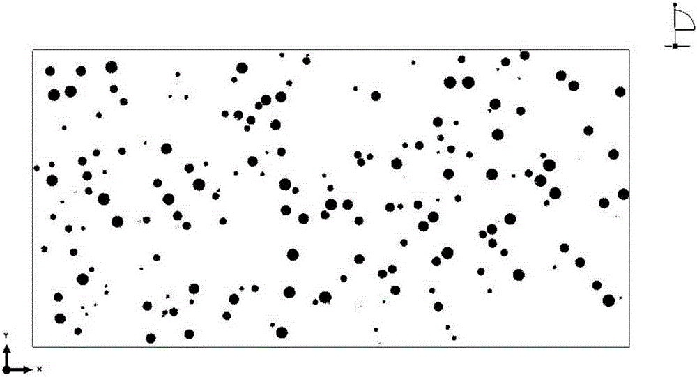
[0059] figure 2 is the defect-containing material model established in Embodiment 1 of the present invention.
[0060] The finite element modeling method of this embodiment is as follows:
[0061] (1) Simplify the pore shape in the defect material to obtain the defect sample.
[0062] The pore shape of the defective material presented by the scanning electron microscope was observed to be irregular and nearly circular, and it was simplified into a two-dimensional circular hole to obtain a defect sample.
[0063] (2) Establish a program for generating data models of defect samples in the command window of MATLAB software.
[0064] Define the pore parameters: the pore distribution range is [0,100:0,50]; the pore shape is a two-dimensional circle, the pore size parameters are the minimum pore radius of 1 μm, the maximum pore radius of 1 μm; the porosity is 0.05. Define the two-dimensional thermal barrier coating material whose defect material parameter is 100μm*50μm. Define ...
Embodiment 2
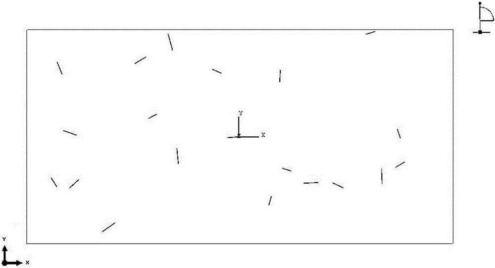
[0098] image 3 is the defect-containing material model established in Embodiment 2 of the present invention.
[0099] The method of establishing a two-dimensional finite element model of a material with randomly distributed linear cracks is as follows:
[0100] (1) Write the program in the command window of MATLAB software.
[0101] Introduction to procedure 2: The linear cracks are distributed in 100μm*50μm. Here, the maximum half length of the crack is 2μm, the minimum half length is 1μm, and the number of cracks is 20. It is assumed that the two straight line cracks do not intersect.
[0102] (2) Import the extracted data into ANSYS, the specific steps and operations are the same as the steps (2) to (4) in the first embodiment.
[0103] (3) input order in ANSYS software, operation step is with the step (5) (6) (7) (9) in the embodiment one; Concrete order is as follows:
[0104] Input command 1: *dim, dd, table, row number, column number (click the Enter key)
[0105] ...
Embodiment 3
[0119] Figure 4 It is the defect-containing material model established in the third embodiment of the present invention.
[0120] The method of establishing a two-dimensional finite element model of a material with randomly distributed linear cracks is as follows:
[0121] (1) Write the program in the command window of MATLAB software.
[0122] Introduction to program 3: Create a three-dimensional material of 100μm*50μm*50μm, randomly distribute three-dimensional circular holes, here the maximum radius of the pores is 1μm, the minimum radius is 1μm (for convenience, you can modify it yourself), the porosity is the ratio of the pores to the total material The proportion of the volume is 5%, assuming that the two circular holes do not intersect.
[0123] (2) Import the extracted data into ANSYS, the specific steps and operations are the same as the steps (2) to (4) in the first embodiment.
[0124] (3) input order in ANSYS software, step and operation are as follows with ste...
PUM
 Abstract
Description
Claims
Application Information