
Magnetic field modulation type stator-rotor mixed permanent magnet memory motor

A hybrid permanent magnet and magnetic field modulation technology, which is applied to synchronous motors with stationary armatures and rotating magnets, magnetic circuit rotating parts, magnetic circuit shape/style/structure, etc., can solve limited applications, hysteresis loss, Difficult to adjust and other issues, to achieve the effect of high space utilization, high electromagnetic conversion efficiency, improved power density and torque capacity

Inactive Publication Date: 2015-12-30
SOUTHEAST UNIV
View PDF6 Cites 13 Cited by
  • Summary
  • Abstract
  • Description
  • Claims
  • Application Information

AI Technical Summary

Problems solved by technology

However, there are hysteresis loss and eddy current loss in the core of the existing magnetic field modulation motor, and the air gap magnetic field is generated by the excitation of NdFeB permanent magnets, which is difficult to adjust, which limits its application in the wide speed regulation drive of electric vehicles

Method used


Image

  • Magnetic field modulation type stator-rotor mixed permanent magnet memory motor
  • Magnetic field modulation type stator-rotor mixed permanent magnet memory motor
  • Magnetic field modulation type stator-rotor mixed permanent magnet memory motor

Examples


Embodiment Construction

[0016] Below in conjunction with accompanying drawing and embodiment mode, the patent of the present invention is described in further detail:

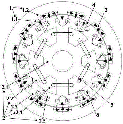
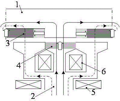
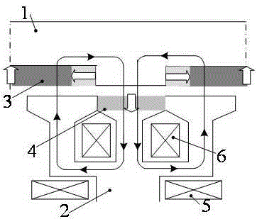
[0017] Such as Figure 1-3 As shown, the present invention discloses a magnetic field modulation stator-rotor hybrid permanent magnet memory motor, the motor includes a rotor 1 and a stator 2, the rotor 1 is located outside the stator 2, and the rotor 1 is rotatably connected to the support shaft through a bearing; , NdFeB permanent magnets 3 with Halbach-type magnetization and alternating pole distribution are embedded on the rotor yoke 1.2 at equal intervals along the circumferential direction. It is recessed along the radial direction of the ring, and the recess is the placement position of the NdFeB permanent magnet 3 .

[0018] The stator 2 includes a stator yoke 2.1, a stator core 2.2 of six multi-tooth structures uniformly distributed in the circumferential direction between the stator yoke 2.1 and the rotor 1, a three-phase a...


PUM


Abstract

The invention discloses a magnetic field modulation type stator-rotor mixed permanent magnet memory motor of high torque density. The motor comprises a rotor and an inner stator, the rotor is located outside the stator and is of a cylindrical-cup-shaped structure as a whole. Rotor salient poles are extended in the radius direction. Neodymium-iron- boron permanent magnets are arranged among the rotor salient poles, wherein Hal Bach type poles are distributed in an alternative mode. The inner stator comprises a stator yoke, six stator cores of multi-tooth structures, three-phase armature windings and pulse magnet regulating windings, wherein the stator cores are arranged between the stator yoke and the rotor and evenly distributed in the peripheral direction. Each stator core is composed of a plurality of stator teeth, and aluminum- nickel-cobalt permanent magnets capable of conducting bidirectional magnetization are arranged between adjacent stator teeth. The three-phase armature windings are wound around every two adjacent stator cores and placed in grooves formed by every two adjacent stator cores. The single-phase pulse magnet regulating windings are placed into grooves formed in the two sides of each aluminum- nickel-cobalt permanent magnet. According to the magnetic field modulation type stator-rotor mixed permanent magnet memory motor, bidirectional modulation of a stator-rotor bilateral mixed permanent magnetic field is achieved through multi-tooth stator poles and the rotor salient poles, so that low-speed large torque can be achieved; meanwhile, a pulse current can be applied for adjusting the residual magnetization intensity and magnetization direction of the permanent magnets, efficient regulation of a motor no-load air gap magnetic field is achieved, the rotation speed potation range is broadened, and thus the magnetic field modulation type stator-rotor mixed permanent magnet memory motor is quite applicable to the field of wind direct-drive power generation.

Description

technical field [0001] The invention relates to an adjustable magnetic flux direct-drive permanent magnet motor, in particular to a novel magnetic field modulation stator-rotor hybrid permanent magnet memory motor. Background technique [0002] In the field of motors, due to the inherent characteristics of ordinary permanent magnet materials (such as NdFeB), the air gap magnetic field in the motor is basically kept constant, and the speed regulation range is very limited when operating as an electric motor. The application of wide-speed adjustable direct drive applications such as electric vehicles and aerospace is limited to a certain extent. Therefore, the adjustable flux permanent magnet motor aimed at realizing the effective adjustment of the air gap magnetic field of the permanent magnet motor has always been a hot spot and difficulty in the field of motor research. . Traditional PMSMs use direct-axis current for field-weakening speed regulation, but it is difficult to...

Claims


Application Information

Patent Timeline
IPC IPC(8): H02K21/22H02K21/04H02K1/27
Inventor 林鹤云阳辉房淑华黄允凯
Owner SOUTHEAST UNIV
Learn More