
Differential-mode feedback circuit

A feedback circuit, differential mode technology, applied in the direction of logic circuit connection/interface layout, electrical components, differential amplifiers, etc., can solve the problems of single, beyond the protocol range, small transmitter output swing, etc. Strong implantation, low noise and interference effect

Active Publication Date: 2015-12-30
SOI MICRO CO LTD
View PDF5 Cites 3 Cited by
  • Summary
  • Abstract
  • Description
  • Claims
  • Application Information

AI Technical Summary

Problems solved by technology

[0003] In 2002, TI proposed a MLVDS technology derived from LVDS, aiming to solve the problem of single line interconnection between multiple transmitters and multiple receivers
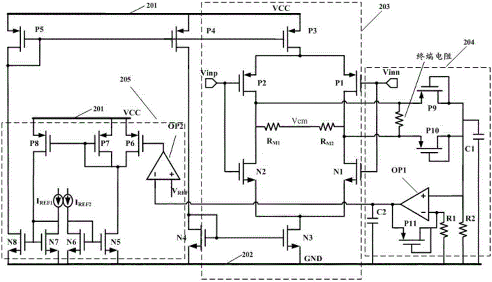
In the current environment where most LVDS transmitters adopt the current mode (CML) structure, the change of the bus load will cause the output swing of the transmitter to be too large or too small, beyond the scope of the protocol

Method used


Image

  • Differential-mode feedback circuit
  • Differential-mode feedback circuit

Examples


Embodiment Construction

[0021] In order to make the object, technical solution and advantages of the present invention clearer, the embodiments of the present invention will be described in detail below with reference to the accompanying drawings.

[0022] Embodiments of the present invention are described in detail below, examples of which are shown in the drawings, wherein the same or similar reference numerals designate the same or similar elements or elements having the same or similar functions throughout. The embodiments described below by referring to the figures are exemplary only for explaining the present invention and should not be construed as limiting the present invention.

[0023] The following disclosure provides many different embodiments or examples for implementing different structures of the present invention. To simplify the disclosure of the present invention, components and arrangements of specific examples are described below. Of course, they are only examples and are not int...


PUM


Abstract

The invention provides a differential-mode feedback circuit. The differential-mode feedback circuit comprises a transmitter body circuit, a differential-mode sampling circuit and a feedback circuit. The transmitter body circuit comprises a third PMOS, a fourth PMOS, a fifth PMOS, a third NMOS, a fourth NMOS and a complementary bridge type switching tube, and the complementary bridge type switching tube is composed of a first PMOS switching tube, a second PMOS switching tube, a first NMOS switching tube, a second NMOS switching tube, a first load resistor and a second load resistor. The differential-mode sampling circuit comprises a ninth PMOS current mirror tube, a tenth PMOS current mirror tube, an eleventh PMOS current mirror tube, a first operational amplifier, a first resistor and a second resistor. The feedback circuit comprises a fifth NMOS current mirror tube, a sixth NMOS current mirror tube, a seventh NMOS current mirror tube, an eighth NMOS current mirror tube, a sixth PMOS current mirror tube, a seventh PMOS current mirror tube, an eighth PMOS current mirror tube and a second operational amplifier. The differential-mode feedback circuit can solve the problem that because the load impedance of an MLVD transmitter is influenced by bus impedance, the differential output amplitude is not stable. The circuit is simple in structure and easy to realize, and can improve the capacity of the transmitter for adapting to impedance changes in bus application and reduce overshoot of output signals.

Description

technical field [0001] The invention relates to the technical field of IC design, in particular to a differential mode feedback circuit applied to a multi-point low-voltage differential signal transmitter. Background technique [0002] With the advent of the era of big data, the rapid processing and high-speed transmission of data has become a focus of attention. In this context, the interface has become a bottleneck restricting high-speed data transmission. As an upgrade of RS482 in speed and function, MLVDS (Multi-point Low-Voltage Differential Signaling, multi-point low-voltage differential signal) technology proposed by TI company came into being. MLVDS technology has many advantages such as high transmission speed of LVDS technology, strong anti-noise ability, low power consumption, low electromagnetic radiation, etc., and can be applied to multi-point bus system to complete the mutual communication between multiple drivers and multiple receivers. [0003] In 2002, TI...

Claims


Application Information

Patent Timeline
Patent Type & Authority Applications(China)
IPC IPC(8): H03K19/0175H03F3/45
CPCH03F3/45237
Inventor 赵建中曹成成蒋见花刘海南周玉梅
Owner SOI MICRO CO LTD
Learn More