
Method and system for preventing fouling of surfaces

An anti-fouling, surface-emitting technology, applied in the direction of pollution prevention methods, cleaning methods and utensils, chemical instruments and methods, etc., can solve the problems of water inlet blockage, increased drag of the hull, etc.

Active Publication Date: 2015-12-30
KONINKLJIJKE PHILIPS NV
View PDF9 Cites 23 Cited by
  • Summary
  • Abstract
  • Description
  • Claims
  • Application Information

AI Technical Summary

Problems solved by technology

The machine stopped working, the water intake was clogged, and the hull suffered increased drag

Method used


Image

  • Method and system for preventing fouling of surfaces
  • Method and system for preventing fouling of surfaces
  • Method and system for preventing fouling of surfaces

Examples


Embodiment Construction

[0073] While the disclosure has been illustrated and described in detail in the drawings and foregoing description, such illustration and description are to be considered illustrative or exemplary and not restrictive; the disclosure is not limited to the disclosed embodiments. It is also to be noted that the drawings are schematic and not necessarily to scale and that details not necessary for an understanding of the invention may have been omitted. The terms "upward", "downward", "below", "above" etc. refer to the embodiment as oriented in the drawings unless otherwise specified. Additionally, elements that are at least substantially the same or perform at least substantially the same function are labeled with the same reference numerals.

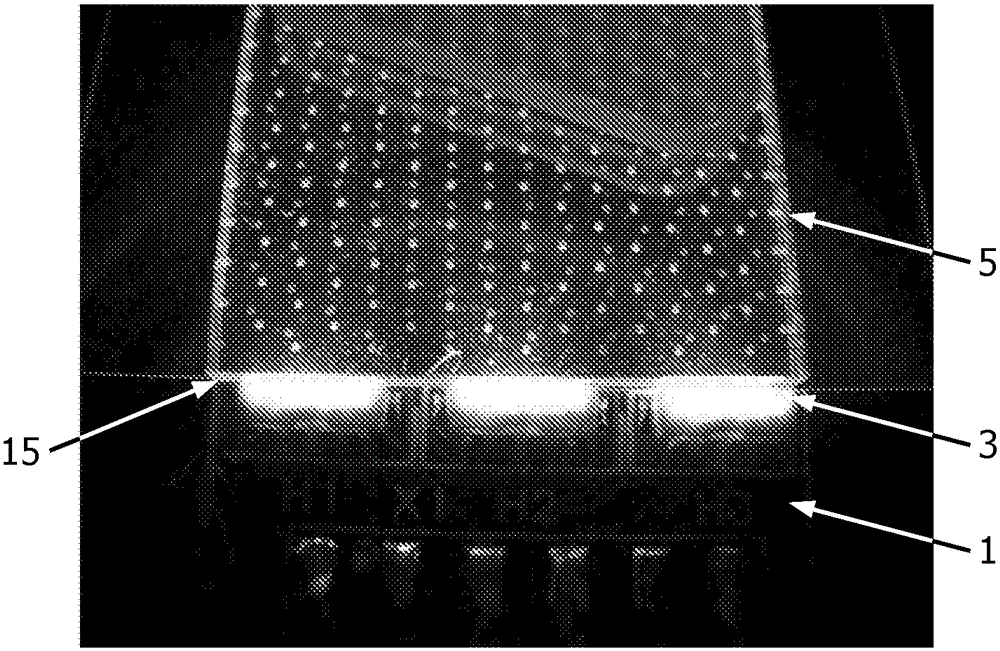
[0074] Figure 7 A cross-section is shown as a basic embodiment of a lighting module 1 comprising a plurality of light sources 3 enclosed in a liquid-tight optical medium 5 to guide at least part of the light 9 emitted from the light sour...


PUM


Abstract

A method of anti-fouling of a surface while said surface is at least partially submersed in an liquid environment comprises providing an anti-fouling light (9); distributing at least part of the light (9) through an optical medium (5) comprising a silicone material and / or UV grade fused silica; emitting the anti-fouling light (9) from the optical medium (5) and from the surface.

Description

technical field [0001] The present disclosure relates to methods for preventing fouling of surfaces (or commonly referred to as anti-fouling) and to apparatus for performing these methods. The present disclosure particularly relates to methods and apparatus for anti-fouling of ship hulls. Background technique [0002] Biofouling or biological fouling is the accumulation of microorganisms, plants, algae and / or animals on surfaces. The diversity among biofouling organisms is highly variable and extends well beyond barnacle and algae attachments. According to some estimates, more than 1700 species including more than 4000 organisms are responsible for biofouling. Biofouling is divided into microfouling, which includes biofilm formation and bacterial adhesion, and macrofouling, which is the adhesion of larger organisms. These organisms are also classified as hard or soft fouling types due to the different chemistry and biology that determine what prevents the organisms from s...

Claims


Application Information

Patent Timeline
Patent Type & Authority Applications(China)
IPC IPC(8): B08B17/02B63B59/04G02B6/00
CPCB08B17/02G02B6/0036G02B6/0043B63B59/04G02B6/00G02B6/0078B01J19/123B08B7/0057G02B19/0061A61L2/10G02B19/0019
Inventor B.A.萨特斯R.B.希伊特布林克I.W.J.M.鲁特坦H.范豪坦
Owner KONINKLJIJKE PHILIPS NV
Learn More