
Polishing machine

A polishing machine and casing technology, which is applied in the field of polishing machines, can solve the problems of reducing tool output efficiency, inconvenient polishing machine assembly, high energy consumption of polishing machines, etc., and achieve the goals of reducing volume and weight, smooth rotation, and improving service life Effect

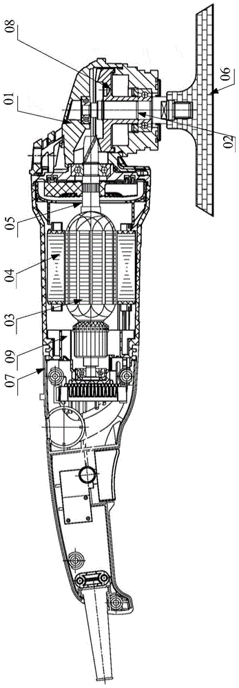
Inactive Publication Date: 2016-01-06
ZHEJIANG LVDONG MOTOR TECH CO LTD
View PDF5 Cites 6 Cited by
  • Summary
  • Abstract
  • Description
  • Claims
  • Application Information

AI Technical Summary

Problems solved by technology

This makes the energy loss of the polishing machine large, reducing the output efficiency of the tool, and the wear of the carbon brush 09 and the transmission gear directly affects the service life of the polishing machine, and the wear of the carbon brush 09 produces carbon powder, which has caused certain pollution to the environment; There are many parts in the polishing machine, and the transmission gears meshing with each other will inevitably produce large noise and vibration during the power transmission process, and it is not convenient for the assembly of the polishing machine

Method used


Image

  • Polishing machine
  • Polishing machine
  • Polishing machine

Examples


Embodiment Construction

[0032] The invention discloses a polishing machine to improve output efficiency and service life, avoid environmental pollution, reduce noise and vibration, and facilitate the assembly of the polishing machine.

[0033] The following will clearly and completely describe the technical solutions in the embodiments of the present invention with reference to the accompanying drawings in the embodiments of the present invention. Obviously, the described embodiments are only some, not all, embodiments of the present invention. Based on the embodiments of the present invention, all other embodiments obtained by persons of ordinary skill in the art without making creative efforts belong to the protection scope of the present invention.

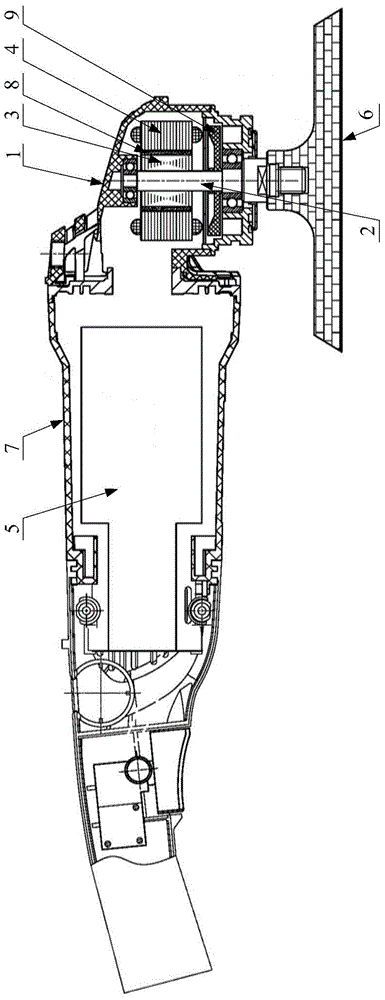
[0034] Please refer to figure 2 , figure 2 Schematic diagram of the structure of the polishing machine provided by the embodiment of the present invention.

[0035] The embodiment of the present invention provides a polishing machine, which includ...


PUM


Abstract

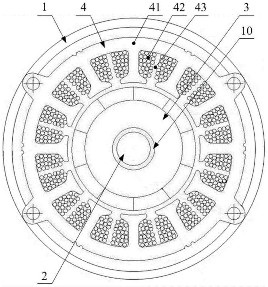
The invention discloses a polishing machine. The polishing machine comprises a machine shell (7) and a head shell (1) arranged at the top end of the machine shell (7), wherein a high-power-density brushless motor is arranged in the head shell (1); a controller (5) of the high-power-density brushless motor is arranged in the machine shell (7); the high-power-density brushless motor comprises a rotor shaft (2) rotationally arranged on the head shell (1), and the rotor shaft (2) and a driving shaft of a polishing rotary disc (6) of the polishing machine are coaxially arranged and are of an integrated structure. The axis of the rotor shaft (2) is perpendicular to the operation surface of the polishing rotary disc (6) and passes through the circle center of the polishing rotary disc (6). According to the polishing machine, the service life of the device is prolonged, generation of carbon powder is avoided, and environmental pollution is avoided. A transmission device is arranged in the machine shell, the service life is prolonged, energy consumption is lowered, output efficiency is improved, and noise and vibration are lowered. The trouble of engagement installation of transmission gears is omitted, the size and weight of the polishing machine are effectively reduced, and the polishing machine can be assembled conveniently.

Description

technical field [0001] The invention relates to the technical field of polishing equipment, in particular to a polishing machine. Background technique [0002] A polishing machine is an electric tool in which the fabric or other items to be polished pass through the polishing disc of the polishing machine to complete the polishing effect. [0003] Please refer to figure 1 , figure 1 It is a structural schematic diagram of a polishing machine in the prior art. [0004] Wherein, the polishing machine consists of a casing 07, a head shell 01, an output shaft 02, a transmission gear 08 arranged on the output shaft 02, a polishing turntable 06 arranged at the end of the output shaft 02 and a motor with carbon brushes (comprising rotor 03, Stator 04, motor shaft 05 and carbon brush 09) form. The motor is arranged in the casing 07, and the motor shaft 05 is a gear shaft or a gear is arranged at its end, so that it meshes with the transmission gear 08, and then drives the polish...

Claims


Application Information

Patent Timeline
Patent Type & Authority Applications(China)
IPC IPC(8): B25F5/00H02K7/14H02K29/00H02K9/04H02K1/20
Inventor 应时立周加泽
Owner ZHEJIANG LVDONG MOTOR TECH CO LTD
Learn More