Weighing support system of garbage compressor
A garbage compactor and support system technology, applied to presses, manufacturing tools, etc., can solve problems such as high installation accuracy requirements, inconvenient maintenance, and large installation errors, so as to improve equipment safety performance, reduce maintenance costs, and maintain convenient effect
- Summary
- Abstract
- Description
- Claims
- Application Information
AI Technical Summary
Problems solved by technology
Method used
Image

Examples
Embodiment Construction
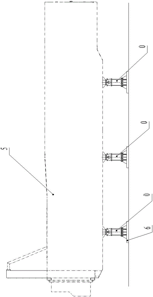
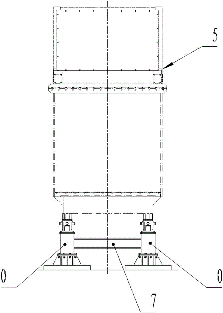
[0032] see Figure 1 to Figure 7 , is an embodiment of the floating weighing support system of the garbage compressor, which is composed of a plurality of contact support mechanisms 0 cooperating with each other, and a connecting beam 7 can also be added between the two contact support mechanisms 0, The strength and stability of the floating weighing support system of the garbage compactor are further enhanced. One end of the contact support mechanism is firmly welded to the garbage compressor 5 , and the other end is firmly welded to the foundation embedded part 6 .
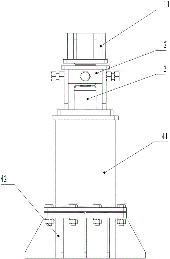
[0033] The contact support mechanism includes a combination support base 4 , a connection base 11 for connecting a garbage compressor, and a load cell 3 . The combined support base includes a base 42 and an upper support base 41, the upper support base is connected and fixed with the base by a plurality of bolts, the upper end of the upper support base 41 is fixed with a weighing mounting base 2, and the load c...
PUM
 Abstract
Description
Claims
Application Information
PatSnap Eureka turns technology decisions into work you can execute. Powered by our Innovation Knowledge Graph, it runs expert workflows across engineering, life sciences, materials and intellectual property. Get your review-ready output in minutes.


