Flapping-wing micro air vehicle based on fan driving

A flapping-wing aircraft and drive technology, applied in the field of flapping-wing bionic aircraft, can solve the problems of large input power, large input power, and heavy weight of the drive, and achieve the effects of simple drive control, convenient processing and manufacturing, and simple structure

Inactive Publication Date: 2016-01-06
NORTHWESTERN POLYTECHNICAL UNIV
View PDF5 Cites 9 Cited by
  • Summary
  • Abstract
  • Description
  • Claims
  • Application Information

AI Technical Summary

Problems solved by technology

Aiming at the disadvantages in the prior art that the structure is complex, the weight is heavy, the input power of the required driver itself is relatively large, the weight of the driver and the difficulty of selecting the driver increase, and the toughness of the driver itself is weak, the present invention proposes a simple structure, high quality The light MFC (Macro-Fiber Composites—large fiber composite material) fan-driven micro-flapping wing aircraft drives the flexible hinge link amplification mechanism through the MFC fan driver to realize the flapping and twisting of the wings; it overcomes the complicated components of the prior art , heavy weight, poor toughness, and require a large input power

Method used


Image

  • Flapping-wing micro air vehicle based on fan driving
  • Flapping-wing micro air vehicle based on fan driving
  • Flapping-wing micro air vehicle based on fan driving

Examples


Embodiment Construction

[0018] This embodiment is a micro-flapping-wing aircraft driven by a fan.

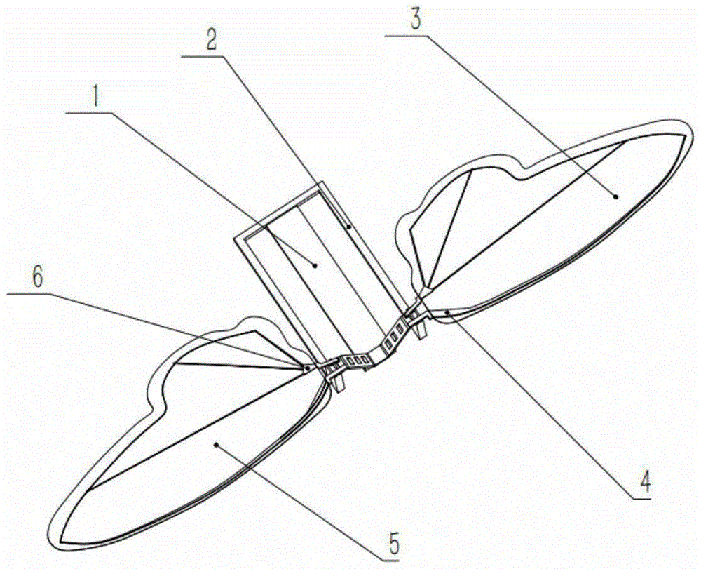
[0019] refer to Figure 1 ~ Figure 4 The micro-flapping wing aircraft combines the fan driver and the hinge linkage mechanism into one body. The hinge linkage mechanism 2 on both sides of the fan driver is symmetrically arranged, and combined with the passive torsion structure, the flapping and twisting of the wings on both sides is realized.

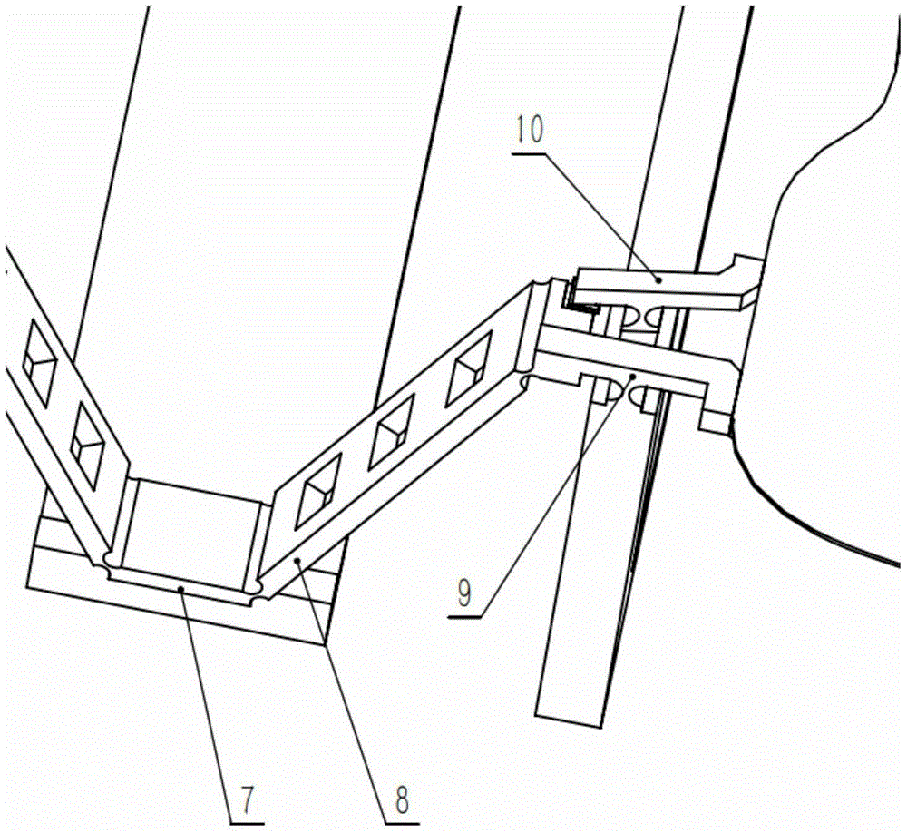
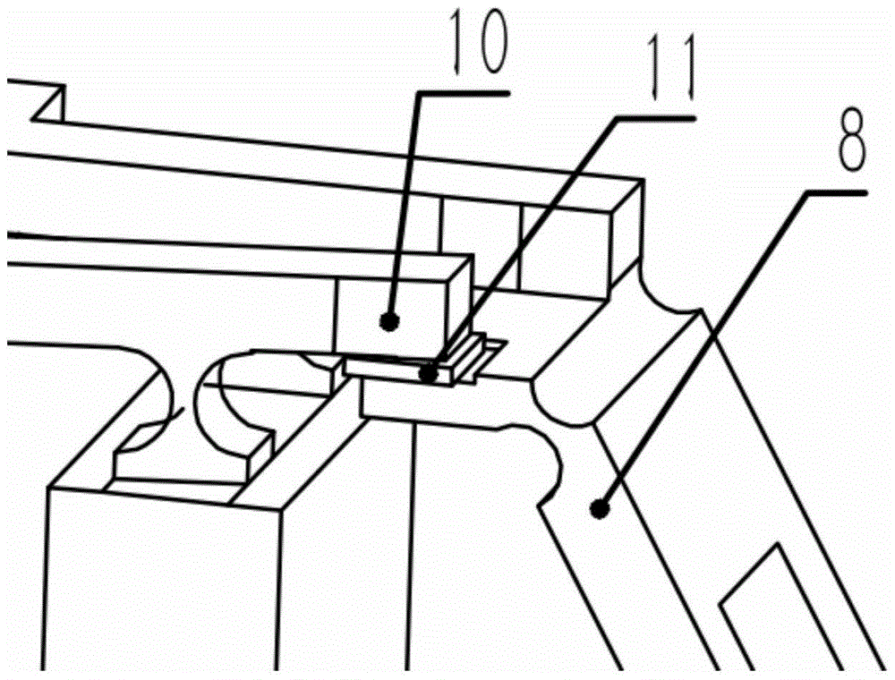
[0020] Present embodiment flapping wing aircraft is by fan driver 1, hinge link mechanism 2, right wing membrane 3, left wing membrane 5, wing leading edge 4, wing trailing edge 6, driver 12, driving fan 13, drive connecting Rod 7, two push rods 8, two control rods 9, two torsion control rods 10, and two wear-resistant pads 11; the fan driver 1 is installed in the hinge linkage mechanism 2, and one end of the fan driver 1 is connected to the hinge The inner end surface of the linkage mechanism 2 is fixedly connected, and the drive link 7 is fixedly installed on...


PUM


Abstract

The invention discloses a flapping-wing micro air vehicle based on fan driving. The flapping-wing micro air vehicle is characterized in that a fan driver is combined with hinged connecting rod mechanisms, is arranged in the hinged connecting rod mechanisms and is fixedly connected with the inner-side end surfaces of the hinged connecting rod mechanisms; the hinged connecting rod mechanisms at two sides are symmetrically arranged; a driving connecting rod is fixed on the free end of the fan driver, and a pushing rod is connected with the driving connecting rod; one end of a control rod is connected with the pushing rod, the other end of the control rod is fixedly connected with the front edges of wings, and the control rod is connected with the hinged connecting rod mechanisms at the side surfaces of the fan driver; a torsion control rod is connected with the hinged connecting rod mechanisms at the side surfaces of the fan driver; one end of the torsion control rod is in contact with a wear-resistant cushion block stuck at the end part of the pushing rod, and the other end of the torsion control rod is connected with the rear edges of the wings; and the up-down vibration of the fan driving mechanism is transferred and amplified under a loading alternating voltage, and the wings are driven by the action of flexible hinges to realize up-down flapping and torsion. The flapping-wing micro air vehicle disclosed by the invention has the advantages that the structure is simple, the processing is convenient and the driving control is simple.

Description

technical field [0001] The invention relates to a flapping-wing bionic aircraft, in particular to a micro-flapping-wing aircraft driven by a fan, belonging to the field of flapping-wing bionic aircraft. Background technique [0002] Micro-flapping-wing aircraft imitates the way of biological flight, and uses the unsteady flow field generated by flapping wings to achieve flight. The flapping frequency of its wings is very high, and its drive mechanism is very important for micro-flapping-wing aircraft to achieve high-efficiency flight similar to that of living things. [0003] The California Institute of Technology proposed a micro-flapping-wing aircraft driving mechanism composed of micro-motors and precision mechanisms; a micro-flapping-wing aircraft driving mechanism based on reciprocating chemical muscles was jointly developed by the University of Cambridge and the Georgia Institute of Technology; Nanjing Airlines Most of the micro-flapping-wing aircraft driving mechanis...

Claims


Application Information

Patent Timeline
Patent Type & Authority Applications(China)
IPC IPC(8): B64C33/02
Inventor 张西金赵宁董强慎玉安闫军杨钱
Owner NORTHWESTERN POLYTECHNICAL UNIV
Why Eureka
Try Eureka