Variable valve lift mechanism and its control method

A valve lift, variable technology, applied in the direction of engine control, mechanical equipment, engine components, etc., can solve the problems of increasing manufacturing costs, pressing rocker arms in advance or delay, affecting the working efficiency and fuel economy of internal combustion engines, etc. Low, linear power output

Active Publication Date: 2018-03-20
JIANGSU HAILONG ELECTRICAL APPLIANCE
View PDF5 Cites 0 Cited by
  • Summary
  • Abstract
  • Description
  • Claims
  • Application Information

AI Technical Summary

Problems solved by technology

However, this structure has the following disadvantages: when the roller follower changes position in the rocker arm, the contact time between the roller follower and the cam will also change, which may cause the rocker arm to be pressed in advance or delayed, and It leads to an unexpected working angle variation range, and additional devices need to be added to correct the camshaft phase
Therefore, if the phase correction device needs to be added when this variable valve lift device is adopted, the manufacturing cost will be increased; and if the phase correction device is not added, the working efficiency of the internal combustion engine and the fuel economy will be affected.

Method used


Image

  • Variable valve lift mechanism and its control method
  • Variable valve lift mechanism and its control method
  • Variable valve lift mechanism and its control method

Examples


Embodiment 1

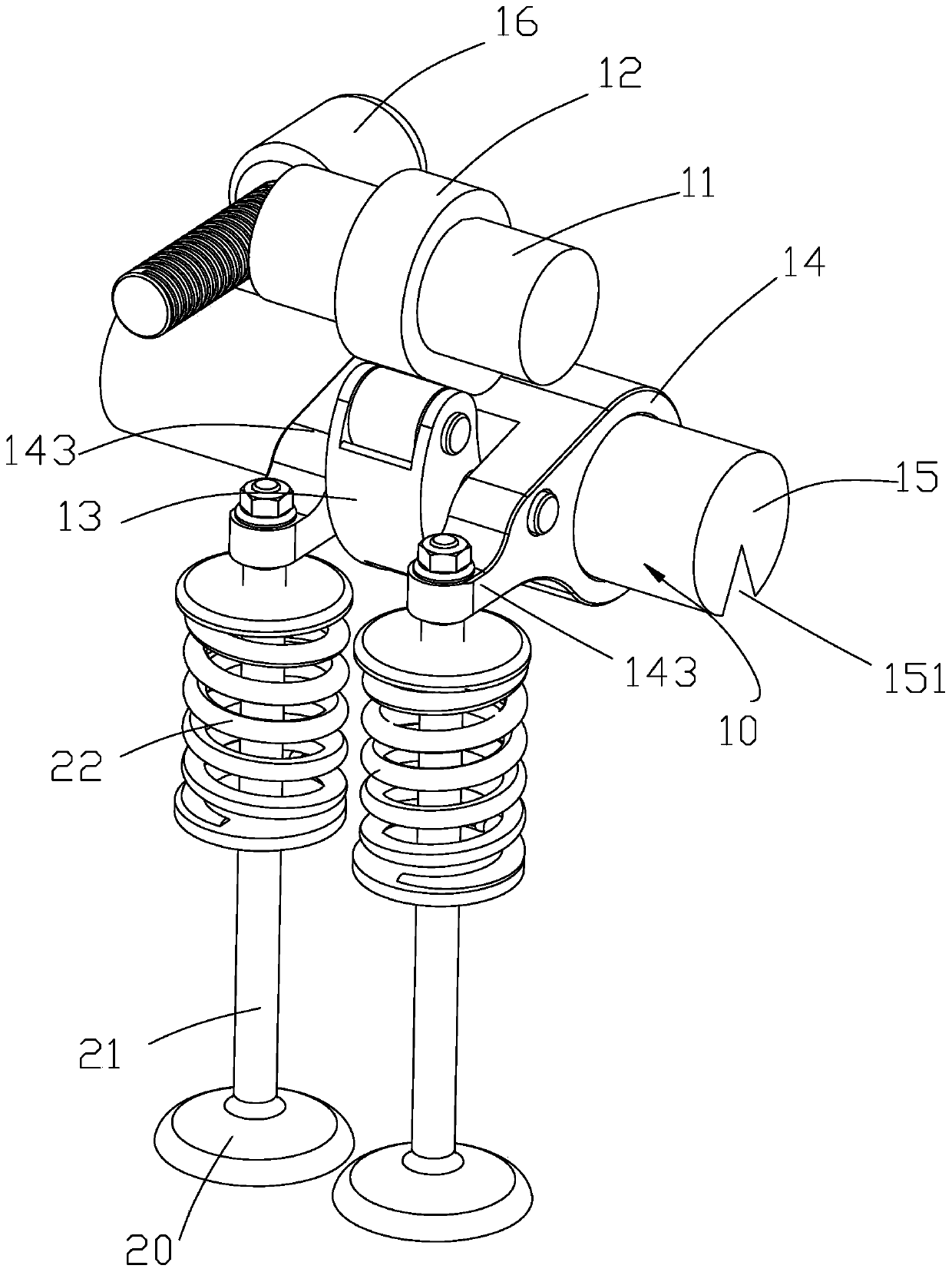
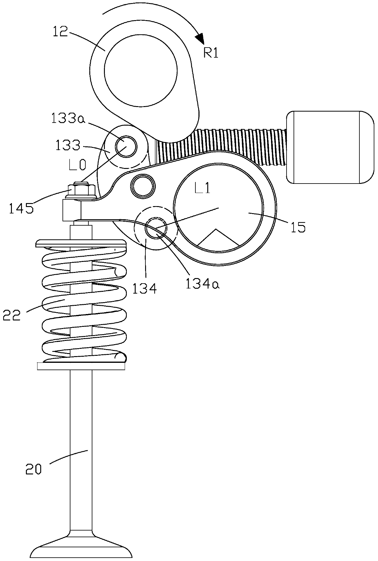
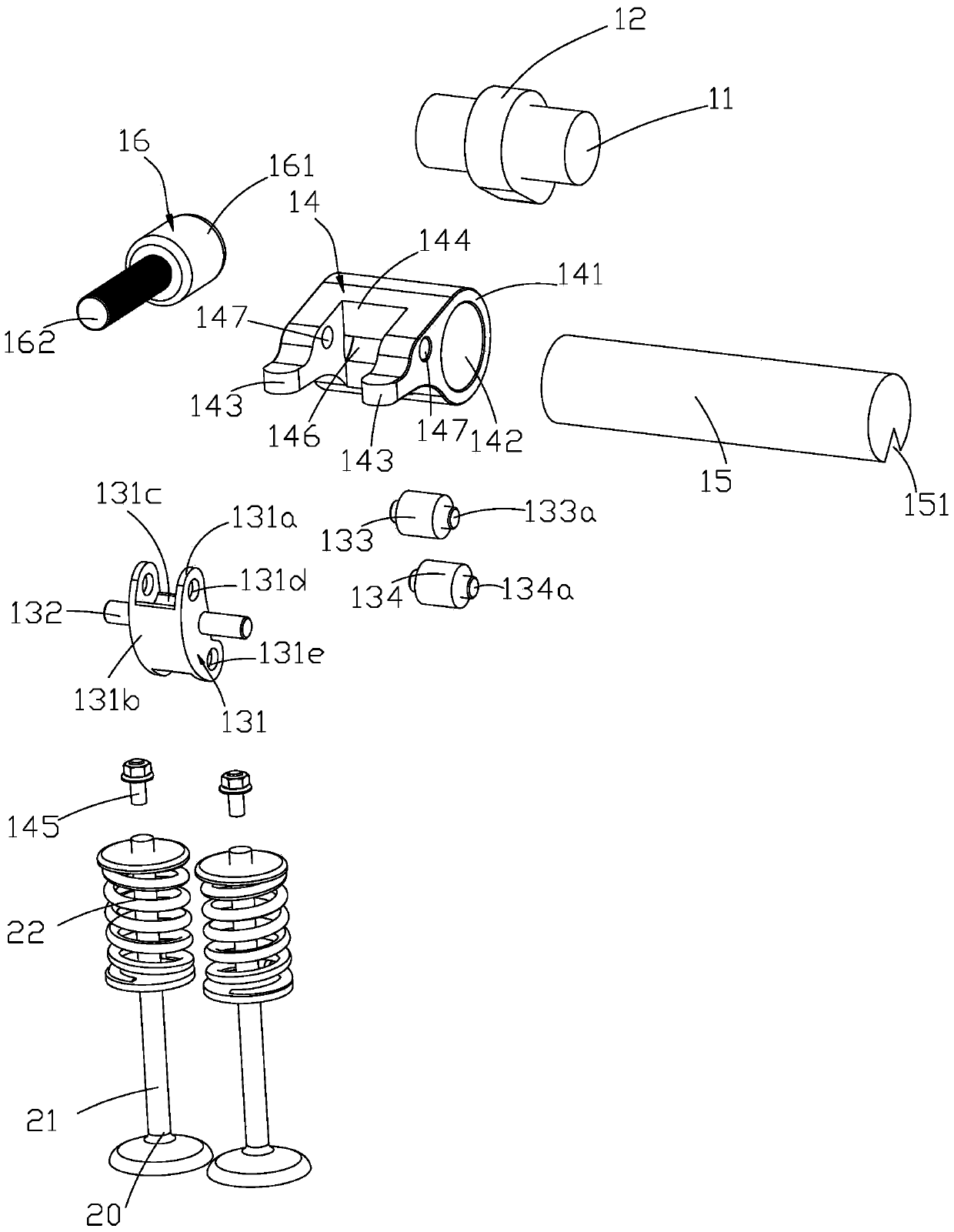
[0076] Figure 1-3 The variable valve lift mechanism 10 in the first embodiment of the present invention is shown, which is used to open and close a valve 20; wherein, the valve 20 can constitute an intake or exhaust system of an internal combustion engine, for example. The valve 20 specifically includes a valve stem 21 and a valve spring 22 sleeved on the valve stem 21.

[0077] Such as Figure 1-3 As shown, the variable valve lift mechanism 10 includes a rotatable camshaft 11, a cam 12 mounted on the camshaft 11, a rocker arm assembly 13 driven by the cam 12 to swing, and a swingable valve 20 to open and close. The swing assembly 14 and the feed shaft 15 rotatably accommodated in the swing assembly 14. In use, the rotation of the camshaft 11 will drive the cam 12 to rotate and drive the rocker arm assembly 13 to swing synchronously in opposite directions, so that the rocker arm assembly 13 drives the swing assembly 14 to swing, thereby driving the opening and closing of the val...

Embodiment 2

[0098] Figure 7-9 The specific structure of the variable valve lift mechanism in the second embodiment of the present invention is shown. Such as Figure 7-9 As shown, the variable valve lift mechanism 10 also includes a cam shaft 11, a cam 12, a rocker arm assembly 13, a swing assembly 14, a feed shaft 15 and a rotation drive assembly 16. Among them, the structures of the cam shaft 11, the cam 12, the rocker arm assembly 13, the feed shaft 15 and the rotation drive assembly 16 are the same as those of the corresponding parts in the first embodiment, and will not be repeated here. The difference between the second embodiment and the first embodiment is that, for the swing assembly 14, the end of each swing arm 143 away from the swing body 141 is further connected to a roller bracket 148, and the roller bracket 148 can also rollably accommodate. Equipped with swing arm roller 149. Wherein, the valve 20 further includes a valve top cup 23 in this embodiment. The valve cleara...


PUM


Abstract

The invention relates to a variable valve lift mechanism and a control method thereof. The variable valve lift mechanism comprises a rotatable cam shaft and a cam installed on the cam shaft and further comprises a rocker arm assembly, a swing assembly and a feeding shaft. The rocker arm assembly is driven by the cam to swing and comprises a regulation and control idler wheel located on one side of the rocker arm assembly. The swing assembly is driven by the rocker arm assembly to swing so as to open and close a valve and provided with a feeding window. The feeding shaft is contained in the swing assembly in a rotatable manner and provided with a feeding groove. When the feeding shaft is rotated, the feeding groove and the feeding window are aligned or staggered. The regulation and control idler wheel makes rolling contact with the feeding shaft through the feeding window, so that the swing assembly is driven to swing. According to the variable valve lift mechanism, no phase correcting device needs to be additionally arranged, the manufacturing cost can be reduced, the valve lift amount can be continuously regulated and controlled, and power output is more linear.

Description

Technical field [0001] The present invention relates to the technical field of valve control equipment, and more specifically, to a variable valve lift mechanism and a control method thereof. Background technique [0002] As we all know, in order to control exhaust gas emissions of internal combustion engines or reduce fuel consumption, it is necessary to change the lift amount of the valve in the intake or exhaust system according to the operating state of the internal combustion engine. [0003] There is a variable valve lift device in the prior art. The device changes the position of the roller in the rocker arm by sliding the roller follower in the guide groove, thereby changing the swing amplitude of the rocker arm driven by the cam to realize the change of the valve lift. This kind of structure is simple and occupies a small space, and the valve can respond quickly. However, this structure has the following shortcomings: when the roller follower changes its position in the ...

Claims


Application Information

Patent Timeline
Patent Type & Authority Patents(China)
IPC IPC(8): F02D13/00F01L13/00
CPCY02T10/12
Inventor 李珍祥
Owner JIANGSU HAILONG ELECTRICAL APPLIANCE
Why Eureka
Try Eureka