Wind power generation system with unipolar DC electromagnetic drive

A technology of wind power generation system and drive train, applied in wind power generation, wind turbine, wind turbine combination, etc., can solve the problem that "narrow-band" speed change cannot meet the optimal speed change requirements, large electromagnetic interference, and unfavorable maintenance and use of double-fed asynchronous generators And other issues

Active Publication Date: 2019-07-30
徐立民
View PDF8 Cites 0 Cited by
  • Summary
  • Abstract
  • Description
  • Claims
  • Application Information

AI Technical Summary

Problems solved by technology

[0007] The currently applied wind power generation systems have the following deficiencies: the constant-speed and two-speed wind rotor operation schemes are far from efficient wind energy capture; The scope basically includes the part below the annual average wind speed, which belongs to the area with the highest wind frequency; the slip ring of the double-fed asynchronous generator is not conducive to maintenance and use; the frequency converter produces electromagnetic noise and harmonics, and the electromagnetic interference is large; The energy loss in the flow process is also relatively large; due to the limited adjustment means and other reasons, the wind energy utilization coefficient Cp of many practically applied wind rotors is significantly lower than the maximum value that can be achieved, including the design point operating conditions and variable speed operating conditions

Method used

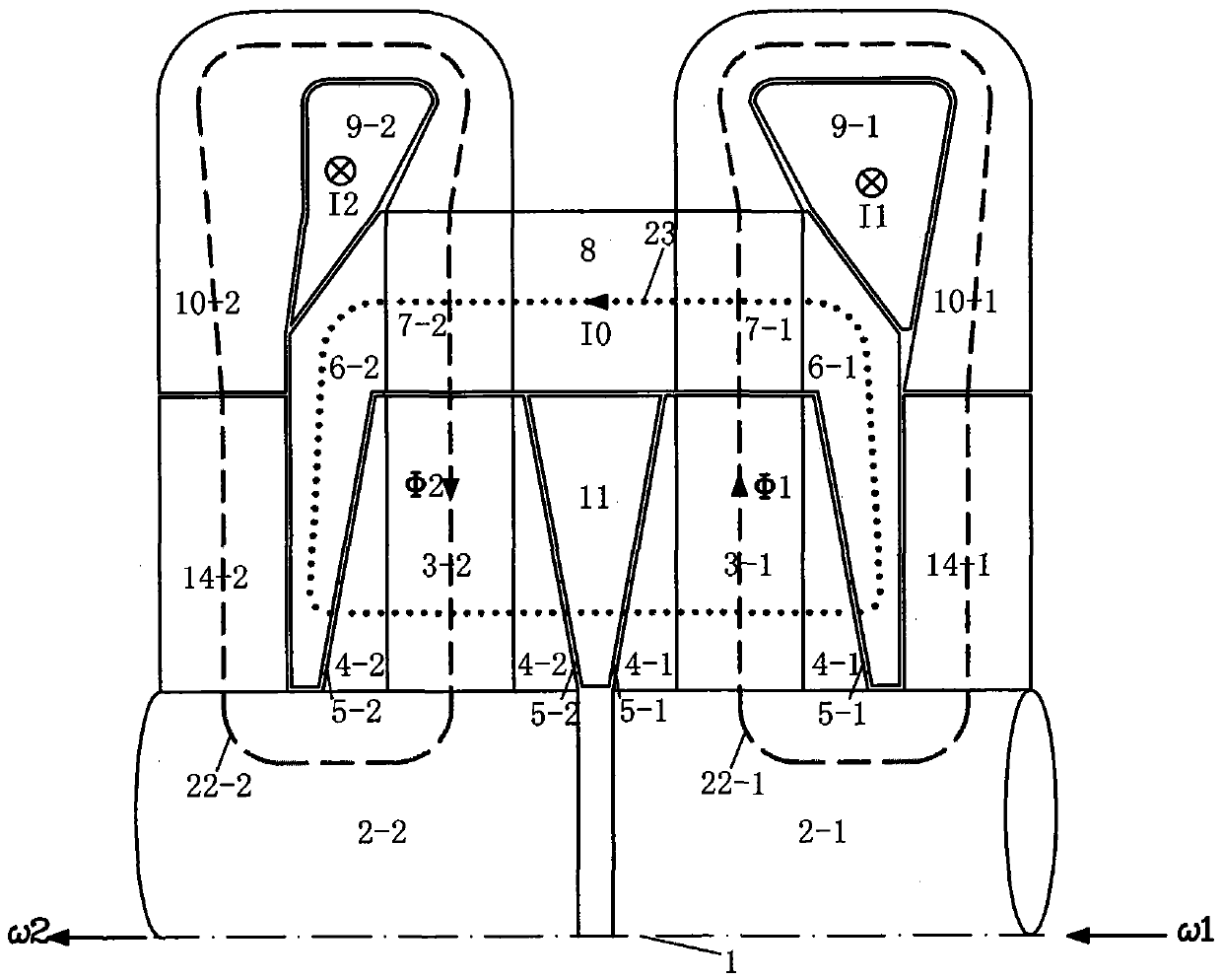
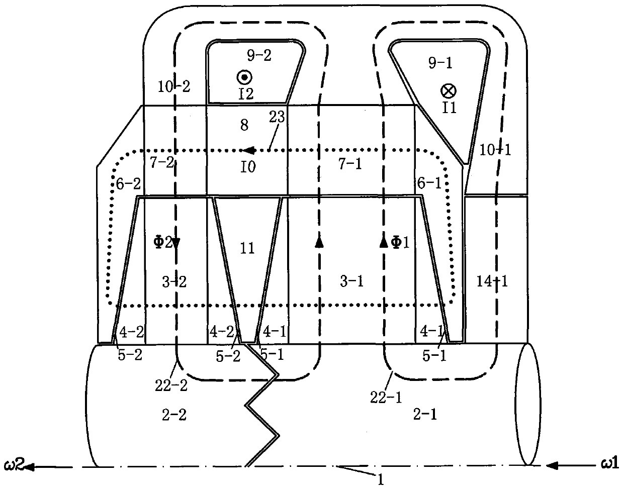
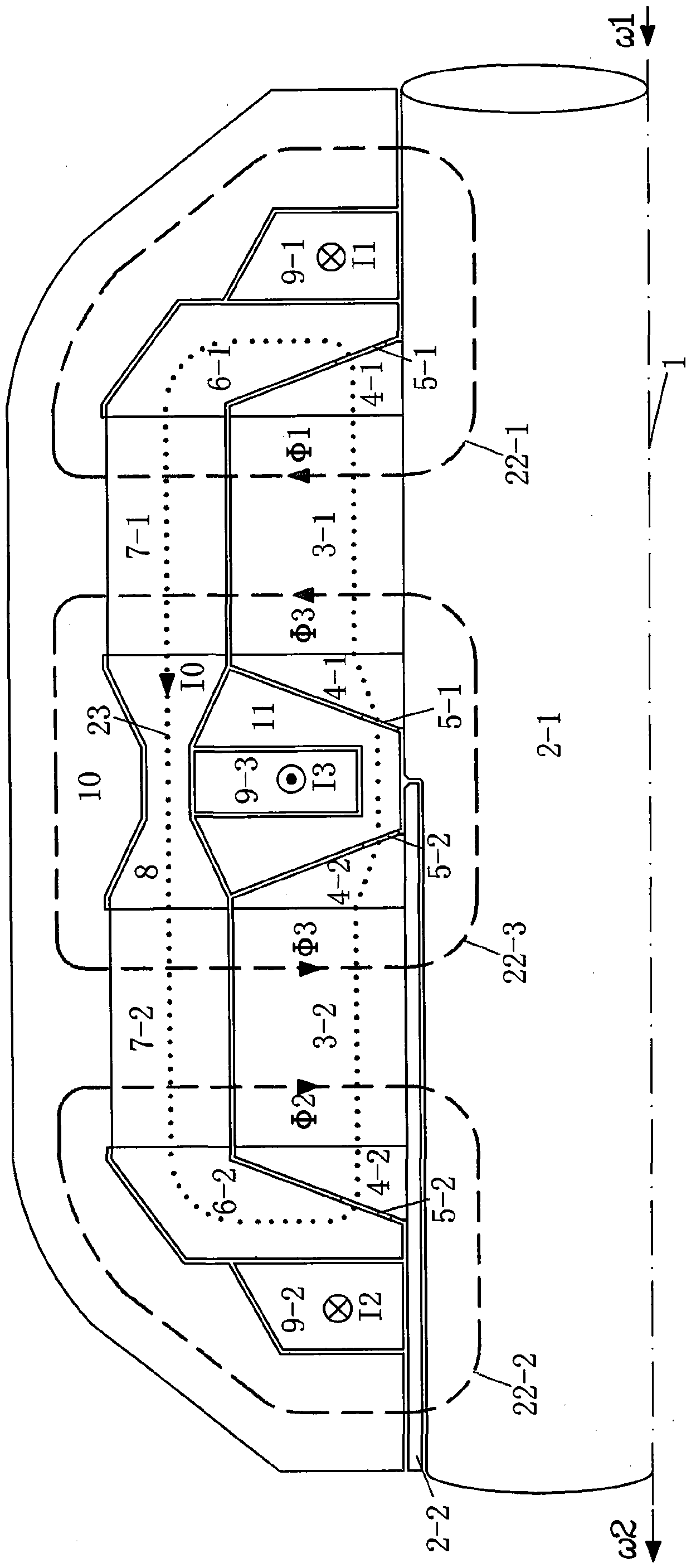

Image

  • Wind power generation system with unipolar DC electromagnetic drive
  • Wind power generation system with unipolar DC electromagnetic drive
  • Wind power generation system with unipolar DC electromagnetic drive

Examples


Embodiment Construction

[0139] A 1.5MW wind power generation system with HET ( Figure 21 ) The specific embodiment is as follows.

[0140] The system includes: a horizontal shaft variable-pitch blade wind rotor, a horizontal speed-up gearbox connected to the wind rotor shaft, a unipolar DC electromagnetic transmission (HET) connected to the gearbox output shaft and the generator shaft, a horizontal A type synchronous generator, a mechanical brake device located at the shaft of the wind rotor, a yaw drive active wind-facing mechanism, a nacelle, a tower, and control and auxiliary systems.

[0141] The wind rotor adopts three airfoil profile blades, the maximum value of wind energy utilization coefficient Cp is 0.47, and the corresponding optimal tip speed ratio is 7, and the rated design point applies the optimal tip speed ratio and the maximum Cp value. Select a rated wind speed of 12m / s for lower wind energy applicable to a wide range of wind fields. The rated speed of the wind rotor is 24.31r / mi...


PUM


Abstract

Provided is a wind power generation system. A homopolar electromagnetic transmission (HET) is adopted as infinitely variable speed and variable torque transmission equipment, the HET is directly connected with a wind wheel and an electric generator, a step-up gearbox is arranged between the wind wheel and the HET, the wind wheel can be in a horizontal shaft type or in a vertical shaft type, the horizontal shaft type wind wheel can be provided with fixed-pitch blades or variable-pitch blades, and the electric generator can be a conventional constant-speed moving synchronous electric generator or asynchronous generator. The operation of the system is mainly adjusted and controlled by the HET, and the wind wheel keeps the optimal tip speed ratio and variable rotation speed to operate under the conventional operation conditions. The wind power generation system has the advantages that the infinitely variable speed and variable torque transmission function with the rotation speed of the two ends being free and not limited is achieved; the flexible transmission connection isolates the bidirectional transferring of impact loads; the largest wind energy capturing efficiency is obtained; the power supply quality is high; the HET is higher in efficiency, lower in cost and small in electromagnetic interference, and does not generate electromagnetic noise and harmonic waves.

Description

[0001] Technical field [0002] The invention relates to a wind power generation system, in particular to a wind power generation system with a continuously variable transmission. Background technique [0003] The source of the wind power generation system is the wind rotor that absorbs wind energy. The rear end has a generator. The speed of the former is very low. Usually, a speed-increasing gearbox is used to connect the two. Drive" scheme (the size and weight of the generator are very large, and there is no popularization and application). The wind wheel has a horizontal shaft type and a vertical shaft type. The horizontal shaft type is generally used, and most of them use three blades and airfoil blades. The blade whose blade root has a structure that rotates with the radial centerline of the blade body as the central axis is called "Variable pitch (angle)" blades, blades without such a rotating structure are called "fixed pitch (angle)" blades, both of which are used. ...

Claims


Application Information

Patent Timeline
Patent Type & Authority Patents(China)
IPC IPC(8): F03D15/00F03D9/25
CPCY02E10/72
Inventor 徐立民
Owner 徐立民
Why Eureka
Try Eureka